Moving walkway safety depends on multiple protective systems working together rather than a single emergency device. Passenger-interface protection, braking systems, motion monitoring, electrical safety circuits, and mechanical fault detection address different hazards during continuous operation.
Typical protective functions include comb plate protection, handrail entry protection, emergency stop devices, overspeed monitoring, anti-reversal protection, pallet or chain monitoring, braking systems, and electrical fault protection.
The exact safety configuration depends on the moving walkway design, inclination, operating environment, and applicable safety requirements.
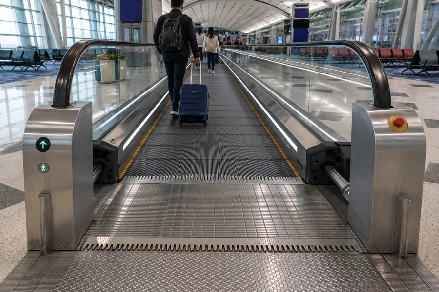
How Moving Walkway Safety Works
A useful way to understand moving walkway safety is through the complete protection chain:
Hazard or abnormal condition → Detection → Safety circuit response → Drive interruption and/or braking → Equipment stops → Fault inspection → Safe reset
Different devices enter this sequence at different points.
For example:
Object enters comb area → Comb protection detects abnormal movement → Safety circuit responds → Moving walkway stops
or:
Abnormal speed detected → Speed monitoring responds → Drive and braking system act → Equipment stops
This layered approach is more important than the number of individual safety devices because each device needs to perform a defined function within the complete system.
[IMAGE POSITION 2 — Technical moving walkway safety architecture diagram showing hazard, sensor, safety circuit, brake, stop, and maintenance inspection]
Main Moving Walkway Safety Features
| Safety Feature | Primary Function | Main Hazard Addressed |
|---|---|---|
| Emergency stop device | Allows manual stopping during an emergency | Continuing operation during a hazardous condition |
| Comb plate protection | Detects abnormal conditions at the pallet-to-comb interface | Object entrapment or impact |
| Handrail entry protection | Detects obstruction at the handrail inlet | Finger, clothing, or object entrapment |
| Service and auxiliary braking | Controls stopping under required operating conditions | Uncontrolled movement |
| Overspeed monitoring | Detects abnormal operating speed | Excessive speed |
| Anti-reversal protection | Detects or prevents unintended reverse movement where applicable | Rollback |
| Pallet monitoring | Detects abnormal pallet position or movement | Uneven or displaced moving surface |
| Chain monitoring | Detects relevant chain abnormalities | Drivetrain failure |
| Electrical safety circuit | Coordinates required protective responses | Unsafe continued operation after a detected fault |
| Fault diagnostics | Records operating abnormalities | Difficult troubleshooting and recurring faults |
Remote monitoring and predictive maintenance can support safety management, but they should be distinguished from the primary safety devices that directly detect hazards or stop the equipment.
Passenger Protection Systems
Passenger-interface areas deserve particular attention because this is where people interact directly with moving components.
Comb Plate Protection
The comb area forms the transition between the moving pallets and the stationary landing.
Foreign objects or abnormal contact at this interface can create an entrapment or mechanical damage risk.
Comb plate protection is designed to detect an abnormal condition at this transition and initiate the required protective response.
[IMAGE POSITION 3 — Close-up technical illustration of moving walkway comb plate, moving pallet, trapped-object zone, and protection mechanism]
Maintenance should therefore inspect not only the protective device but also:
-
Comb teeth
-
Pallet alignment
-
Foreign-object accumulation
-
Fasteners
-
Mechanical movement around the comb area
A functioning switch cannot compensate for damaged or poorly aligned mechanical components.
Handrail Entry Protection
The handrail disappears into the balustrade at the inlet or return area, creating another potential interaction point.
Handrail entry protection addresses objects such as:
-
Fingers
-
Clothing
-
Luggage straps
-
Loose objects
If an obstruction activates the protective device, the system initiates the required stop response.
[IMAGE POSITION 4 — Moving walkway handrail inlet protection diagram showing handrail entry point and obstruction detection zone]
The handrail system itself also needs correct tension, tracking, surface condition, and movement relative to the passenger-carrying surface.
Emergency Stop Devices
Emergency stop devices provide a manual means of stopping the moving walkway when a hazardous condition is observed.
Their effectiveness depends on more than simply installing the button.
Project and maintenance considerations include:
-
Accessibility
-
Visibility
-
Correct electrical function
-
Appropriate placement
-
Inspection and functional testing
The emergency stop is therefore one layer of protection rather than the complete safety strategy.
Passenger-Surface Protection
Other passenger-interface features can include:
-
Slip-resistant pallet surfaces
-
Visible pallet-edge markings
-
Skirt protection features
-
Entrance and exit lighting
-
Warning indicators
-
Appropriate landing geometry
These measures reduce exposure to hazards before an emergency stopping response becomes necessary.
Motion and Braking Safety
Stopping a loaded moving walkway safely requires coordination between the drive, control, monitoring, and braking systems.
Service and Auxiliary Braking
Braking systems provide controlled stopping when operation needs to be interrupted.
Depending on the equipment design and applicable requirements, the system may incorporate more than one braking function to address normal stopping and abnormal operating conditions.
Relevant monitoring can include:
-
Operating speed
-
Direction of movement
-
Brake condition
-
Drive status
-
Encoder information
-
Power-supply abnormalities
The required response depends on which fault has been detected.
Overspeed Protection
Overspeed monitoring identifies operation outside the permitted speed condition.
A simplified protection chain is:
Abnormal speed → Speed detection → Safety response → Drive interruption / braking → Stop
The monitoring system needs to distinguish normal operation from an unsafe speed condition and trigger the designed response when required.
Anti-Reversal Protection
Unintended reverse movement can be particularly important on inclined moving walkways because gravity acts on the passenger and equipment load.
Anti-reversal protection addresses this failure mode by preventing or detecting unintended movement in the opposite direction and initiating the appropriate protective response.
[IMAGE POSITION 5 — Inclined moving walkway diagram showing normal travel direction, rollback hazard, anti-reversal protection, and braking]
Mechanical Monitoring
Some safety-related problems begin as mechanical deterioration rather than an immediate passenger-interface event.
Monitoring and inspection can identify changes before they progress into more serious failures.
Pallet Monitoring
The moving surface needs to remain properly supported and aligned throughout its travel.
Abnormal pallet position, damage, or movement can create an uneven passenger surface or interfere with surrounding components.
Monitoring systems may therefore detect relevant pallet abnormalities and initiate a stop when required by the equipment design.
Chain and Drive Monitoring
Drive and pallet-chain systems operate under repeated mechanical loading.
Inspection or monitoring may address:
-
Chain condition
-
Tension
-
Elongation
-
Synchronization
-
Sprocket condition
-
Abnormal movement
Not every condition is necessarily detected by an automatic sensor. Some deterioration is identified through scheduled inspection and measurement.
This distinction is important because automatic protection and preventive maintenance perform different functions.
Automatic protection responds to defined abnormal conditions during operation.
Preventive maintenance identifies deterioration before it reaches that condition.
Other Mechanical Conditions
Depending on the equipment design and maintenance strategy, technicians may also evaluate:
-
Drive-system vibration
-
Bearing temperature
-
Gearbox condition
-
Guide condition
-
Structural condition
-
Fastener security
-
Pallet alignment
Condition monitoring can support earlier diagnosis, but it does not replace required safety devices or physical inspection.
Electrical Safety and Control Systems
Moving walkway protection depends on electrical circuits that receive signals from protective devices and initiate the required system response.
Relevant components can include:
-
Safety circuits
-
Safety relays
-
Controllers
-
Speed or direction feedback
-
Motor protection
-
Brake monitoring
-
Power-supply protection
-
Fault diagnostics
Typical Electrical Protection Functions
| Function | Purpose |
|---|---|
| Motor protection | Detects relevant overload or abnormal motor conditions |
| Phase or supply protection | Detects electrical supply abnormalities |
| Speed monitoring | Detects operation outside permitted conditions |
| Direction monitoring | Identifies unintended movement where applicable |
| Brake monitoring | Verifies required braking conditions |
| Safety-circuit monitoring | Prevents operation when a required safety condition is not satisfied |
| Fault diagnostics | Records abnormal events for troubleshooting |
The specific architecture varies by manufacturer and system design.
[IMAGE POSITION 6 — Simplified electrical safety diagram showing sensors, safety circuit, controller, drive motor, and braking system]
PLC, Safety Control, and Fault Diagnostics
Control logic and safety functions should not be treated as interchangeable terms.
A conventional PLC may coordinate normal equipment operation and diagnostics, while safety-related functions need to follow the architecture required by the equipment design and applicable safety requirements.
Fault diagnostics provide additional maintenance value by recording conditions that caused a shutdown.
For example:
Repeated fault at the same device → Compare fault history → Inspect corresponding mechanical/electrical condition → Identify root cause → Correct and verify
This is more useful than repeatedly resetting the equipment without determining why the same fault returns.
Remote Monitoring and Predictive Maintenance
Remote condition monitoring can provide maintenance teams with information such as:
-
Equipment operating status
-
Fault history
-
Shutdown events
-
Operating trends
-
Maintenance alerts
This information can support faster troubleshooting and condition-based maintenance.
However, remote monitoring should not be described as a substitute for the primary safety architecture.
Its main role is:
Operational data → Earlier diagnosis → Better maintenance planning
rather than:
Remote monitoring → Direct passenger protection
This distinction keeps maintenance technology and functional safety in their correct engineering roles.
How Multiple Safety Systems Work Together
Consider an object becoming trapped near the comb area.
The complete sequence may involve:
Mechanical abnormality
↓
Comb protection responds
↓
Safety circuit changes state
↓
Drive operation is interrupted
↓
Braking system stops the walkway
↓
Fault condition is investigated
↓
Obstruction and equipment condition are checked
↓
System is reset only after the cause is resolved
[IMAGE POSITION 7 — Eight-stage moving walkway emergency protection workflow from hazard detection to inspection and reset]
The important engineering principle is that the sensor does not provide safety by itself.
Detection, control response, stopping performance, mechanical condition, inspection, and correct reset all contribute to the final outcome.
Hazard-to-Protection Matrix
Rather than listing the same safety devices in several separate tables, the following matrix connects each hazard to its principal protection strategy.
| Potential Hazard | Primary Protection | Additional Engineering Consideration |
|---|---|---|
| Object at comb interface | Comb plate protection | Comb condition, pallet alignment, cleaning |
| Handrail inlet obstruction | Handrail entry protection | Handrail condition and tracking |
| Excessive speed | Speed monitoring and braking response | Drive and feedback condition |
| Unintended reverse movement | Anti-reversal protection where applicable | Braking and drivetrain condition |
| Abnormal pallet position | Pallet monitoring where provided | Pallet and guide inspection |
| Chain deterioration or failure | Monitoring where provided plus inspection | Wear measurement and preventive maintenance |
| Motor abnormality | Motor/electrical protection | Temperature, load, and drivetrain diagnosis |
| Electrical safety fault | Safety circuit protection | Wiring, relay, controller, and device inspection |
| Observed passenger hazard | Emergency stop | Accessibility and functional testing |
This format separates three different layers:
Hazard → Automatic protection → Maintenance or engineering control
That distinction makes it easier to understand what the equipment can detect automatically and what still depends on inspection.
Safety Considerations by Installation Environment
The core safety architecture should follow the equipment design and applicable requirements, but operating environments introduce different risk priorities.
Shopping Malls
Relevant conditions can include:
-
Family groups
-
Children
-
Shopping bags
-
Frequent boarding and exiting
-
Debris around entrances
This increases the importance of passenger-interface protection, cleaning, and visible entrance conditions.
Airports and Transit Facilities
These environments can combine:
-
High passenger volumes
-
Long operating hours
-
Luggage
-
Peak traffic
-
High availability requirements
Fault diagnostics, maintenance access, equipment condition monitoring, and efficient recovery from shutdowns become particularly important.
Hospitals
Hospital applications may place additional emphasis on:
-
Accessible emergency controls
-
Smooth starting and stopping
-
Predictable passenger movement
-
Maintenance planning
-
Equipment availability
Outdoor Installations
Outdoor equipment introduces environmental risks such as:
-
Rain
-
Dust
-
Humidity
-
Temperature variation
-
Corrosion
-
Water ingress
Electrical enclosures, drainage, sealing, corrosion protection, and inspection strategy therefore become part of the safety and reliability plan.
Moving Walkway Safety Standards
Moving walkway projects need to comply with the standards and regulations applicable to the installation location and equipment.
The source material for this article identifies three commonly referenced standards or code families:
| Standard | Region Identified in Source Material | Scope in Project Context |
|---|---|---|
| EN 115 | Europe and international markets | Escalator and moving walkway safety |
| GB 16899 | China | Escalator and moving walkway safety |
| ASME A17.1 | United States and Canada | Elevators, escalators, and moving walks |
These references should not be treated as interchangeable.
Project teams need to establish the applicable code, edition, local adoption, inspection requirements, and authority having jurisdiction before finalizing the safety configuration.
[IMAGE POSITION 8 — Clean technical world-region diagram showing EN 115, GB 16899, and ASME A17.1 as regional moving walkway safety references]
Inspection and Maintenance for Long-Term Safety
Safety devices need to remain functional after commissioning.
Maintenance planning may include:
-
Emergency stop testing
-
Comb-area inspection
-
Handrail operation and protection
-
Chain and drive inspection
-
Brake inspection and testing
-
Speed and direction monitoring
-
Safety-circuit inspection
-
Electrical cabinet inspection
-
Pallet alignment
-
Lubrication
-
Fastener inspection
-
Fault-history review
Inspection frequency should follow the manufacturer, applicable requirements, equipment condition, operating hours, and site environment.
A useful maintenance loop is:
Inspect → Test → Record → Compare → Diagnose → Correct → Verify
Historical records are particularly useful when faults recur because they allow technicians to distinguish an isolated event from a developing pattern.
Safety Feature Selection Checklist
Before finalizing a moving walkway system, project teams should confirm:
| Evaluation Area | Key Question |
|---|---|
| Applicable requirements | Which safety code and local requirements govern the project? |
| Passenger profile | Who will use the walkway and what interaction risks are expected? |
| Inclination | Does the layout introduce rollback or stability considerations? |
| Operating environment | Is the equipment indoors, outdoors, humid, dusty, or otherwise exposed? |
| Braking | Does the braking architecture match the equipment and operating conditions? |
| Passenger interfaces | How are comb, handrail, pallet, and entrance hazards addressed? |
| Mechanical monitoring | Which abnormal conditions are automatically detected and which require inspection? |
| Electrical protection | How are safety-related faults detected and responded to? |
| Maintenance access | Can technicians inspect and test critical components efficiently? |
| Diagnostics | Can shutdown causes and recurring faults be identified? |
| Spare parts | Can safety-critical components be supported throughout the service life? |
The checklist is more useful than comparing the number of advertised safety features because two systems can use different architectures to address the same hazard.
Conclusion
Moving walkway safety is created by a chain of coordinated functions rather than a single protective device.
Passenger-interface systems address hazards around comb plates, handrails, pallets, and entrances. Motion monitoring and braking address abnormal movement. Electrical safety circuits coordinate required responses, while inspection and condition monitoring identify deterioration that automatic devices may not detect.
The core safety logic can therefore be summarized as:
Prevent exposure where possible → Detect abnormal conditions → Stop when required → Diagnose the cause → Verify before returning to service
For architects, contractors, facility managers, and procurement teams, evaluating a moving walkway by this protection logic provides more decision value than simply counting sensors, controllers, or advertised safety features.