Elevator shaft size normally refers to the clear internal width and depth of the hoistway. A usable shaft also needs sufficient pit depth below the lowest landing and headroom above the highest landing.
There is no single shaft size for every elevator of the same capacity. Car dimensions, entrance arrangement, counterweight position, drive system, speed, equipment layout, and construction tolerances can all change the required envelope.
As a preliminary reference, conventional passenger elevator shafts may range from about 2000 × 1700 mm for a 630 kg elevator to about 2600 × 2450 mm for a 1600 kg elevator. Final dimensions must be coordinated with the selected elevator configuration and project drawings.
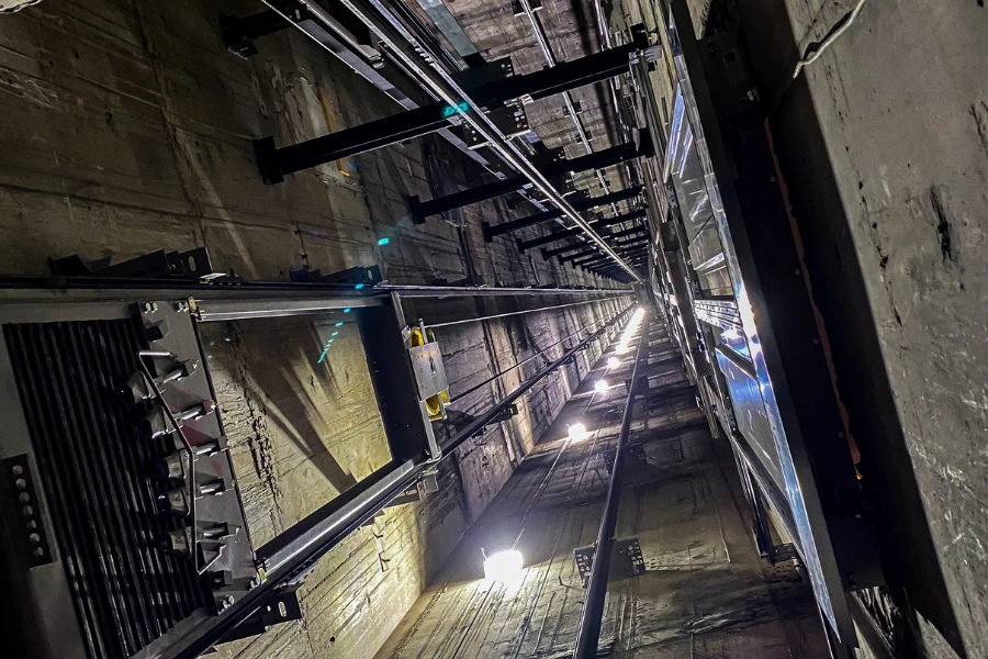
What Does Elevator Shaft Size Mean?
Elevator shaft dimensions are normally expressed as clear width × clear depth. These measurements describe the usable internal space available to the elevator system, not simply the structural opening shown on an architectural plan.
Shaft planning also includes two vertical dimensions.
- Pit depth is the vertical distance below the lowest landing level.
- Headroom is the available vertical space above the highest landing level.
A shaft with sufficient width and depth can therefore remain unusable if its pit or headroom doesn’t accommodate the selected system.
Elevator Shaft Size vs. Car Size
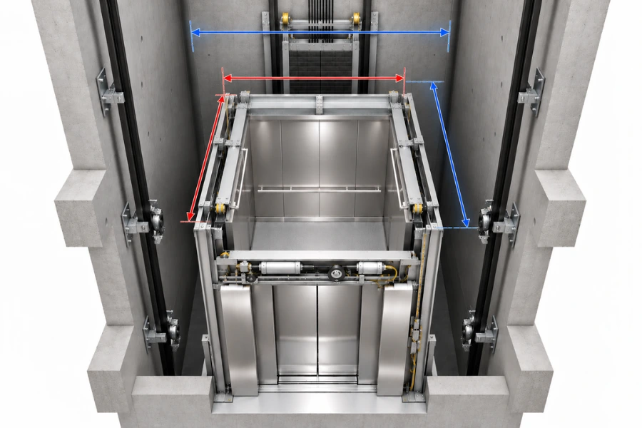
The elevator car occupies only part of the hoistway. Depending on the system, the remaining space may contain:
- Car frame
- Car and counterweight guide rails
- Counterweight
- Rail brackets
- Landing door equipment
- Door panels and operators
- Traveling components
- Operating and safety clearances
- Installation allowances
A 1600 × 1400 mm car therefore doesn’t translate into a shaft size by adding one fixed clearance around it. The final envelope depends on how these components are arranged beside, behind, above, and below the car.
Reference Elevator Shaft Sizes for Preliminary Planning
The following dimensions represent one conventional passenger elevator planning configuration with a machine room and rear counterweight. They can support early space allocation but aren’t universal dimensions for every elevator of the same capacity.
| Rated Load | Typical Capacity | Reference Car Size | Reference Clear Shaft Size |
|---|---|---|---|
| 630 kg | 8 people | 1400 × 1100 mm | 2000 × 1700 mm |
| 800 kg | 10 people | 1400 × 1350 mm | 2000 × 2100 mm |
| 1000 kg | 13 people | 1600 × 1400 mm | 2200 × 2000 mm |
| 1350 kg | 18 people | 1900 × 1600 mm | 2500 × 2300 mm |
| 1600 kg | 21 people | 2000 × 1750 mm | 2600 × 2450 mm |
Different manufacturers can use different car frames, entrances, guide rail layouts, counterweights, and drive arrangements. A capacity-based table is therefore suitable for concept planning, while structural construction should follow the coordinated dimensions of the selected elevator system.
Why Can Elevators With the Same Capacity Need Different Shaft Sizes?
Rated capacity defines how much load the elevator is designed to carry. It doesn’t define how its mechanical components are distributed around the car.
A practical sizing sequence is:
Building use → traffic requirement → rated capacity → car size → entrance configuration → counterweight and rail layout → drive system → clearances → final shaft size
Changes after the capacity decision can therefore change the shaft without changing the elevator’s rated load.
Counterweight Position Changes the Shaft Envelope
A traction elevator requires space for the counterweight, its guide rails, and its travel path.
A rear counterweight generally consumes space behind the car and can increase required shaft depth. A side counterweight places more equipment beside the car and can shift the requirement toward shaft width.
Two elevators with the same rated load and similar usable car area can therefore require differently proportioned shafts.
MRL Doesn’t Automatically Mean a Smaller Shaft
A machine-room-less elevator eliminates a separate conventional machine room. The traction machine and other system components still have to be accommodated within the elevator installation.
The following dimensions compare the two reference configurations supplied for this guide. They illustrate how equipment arrangement can change shaft proportions and aren’t a universal conversion between machine-room and MRL elevators.
| Rated Load | Reference Rear-Counterweight Layout | Reference MRL Side-Counterweight Layout |
|---|---|---|
| 630 kg | 2000 × 1700 mm | 2300 × 1700 mm |
| 800 kg | 2000 × 2100 mm | 2300 × 2000 mm |
| 1000 kg | 2200 × 2000 mm | 2500 × 2000 mm |
| 1350 kg | 2500 × 2300 mm | 2900 × 2400 mm |
| 1600 kg | 2600 × 2450 mm | 3000 × 2400 mm |
An MRL configuration can save space outside the hoistway while requiring equal, greater, or differently proportioned clear space inside it. Machine-room space and shaft space are therefore separate planning variables.
Door Configuration Can Change Shaft Width and Depth
The clear opening seen by passengers is smaller than the complete entrance equipment envelope. Door panels, tracks, hangers, operators, and the space into which panels travel also occupy shaft space.
Relevant arrangements include:
- Center-opening doors
- Side-opening doors
- Front-only entrances
- Front and rear through-car entrances
- Adjacent entrances
Clear door width alone therefore can’t determine shaft width. Panel arrangement and entrance position also control how much equipment must fit beside or around the car.
Through-car and adjacent-opening configurations require additional coordination because they reduce the locations available for other shaft equipment.
Speed Can Affect the Vertical Envelope
Rated speed can change buffer requirements, safety clearances, equipment arrangements, pit depth, and overhead conditions.
A shaft designed around a low-speed elevator can’t automatically be reused for a faster system of the same capacity. Speed should be established before the pit and headroom are structurally fixed.
How Much Pit Depth and Headroom Does an Elevator Need?
Pit and headroom requirements depend on the selected elevator system, rated speed, load, car height, buffers, and equipment design.
The following values are example planning references from the technical material used for this guide. They illustrate configuration sensitivity rather than code minimums.
| Example Configuration | Reference Pit Depth | Reference Headroom |
|---|---|---|
| 630 kg at 1.0 m/s | About 1250 mm | About CH + 1400 mm |
| 1000 kg at 1.6 m/s | About 1300 mm | About CH + 1500 mm |
| Example high-speed configuration above 2.5 m/s | About 1750–2200 mm | Project-specific |
Here, CH refers to car height.
Pit space can accommodate buffers and equipment below the car’s normal lowest position, while headroom provides the vertical envelope needed at the top of travel. Adequate shaft width and depth therefore don’t establish installation feasibility unless the vertical envelope is also confirmed.
How Building Use Changes Elevator Shaft Size
Building use changes shaft planning because the elevator may need to accommodate more than a target passenger count. Wheelchairs, stretchers, medical equipment, luggage, pallets, handling equipment, and different traffic patterns can change the required car proportions and entrances.
Passenger and Commercial Elevators
Passenger elevator sizing should begin with occupancy and traffic demand.
An office building may need to handle concentrated arrival and departure peaks, while a hotel also needs space for luggage and service movements. In multi-elevator buildings, traffic analysis may favor a different combination of car capacity and elevator quantity rather than simply increasing one shaft.
Stretcher and Hospital Elevators
Stretcher requirements depend on the applicable market and project standard.
For projects using the Chinese T/CEA 0029—2023 reference supplied for this guide, stretcher accommodation can use configurations such as:
- A wider car with a long side of at least 1600 mm and a short side of at least 1500 mm
- A deeper car at least 1100 mm wide and 2100 mm deep
- A clear door opening of at least 900 mm
These are car and entrance requirements. They don’t establish a universal stretcher elevator shaft size.
Separate from those T/CEA car and entrance requirements, Chinese tender references may use shaft dimensions around 2500 × 2200 mm or 2200 × 2500 mm for stretcher elevators. These are project examples rather than standardized shaft dimensions and shouldn’t be transferred directly to another elevator configuration or jurisdiction.
Home Elevators
Home elevator shaft requirements vary substantially with drive technology and equipment layout.
| Home Elevator Configuration | Reference Shaft Size |
|---|---|
| Compact home elevator | About 1250 × 1500 to 1600 × 1600 mm |
| 400 kg traction home elevator | About 1500 × 1500 mm |
| Compact screw-driven system | As small as about 1000 × 1200 mm |
Because these references represent different system architectures, they aren’t interchangeable. Space-constrained residential projects should use the selected system’s civil layout before structural openings are fixed.
Freight Elevators
Freight elevator sizing depends on load geometry and handling method as well as rated capacity.
Key inputs include:
- Maximum individual load
- Pallet dimensions
- Pallet jack or other handling equipment
- Required door width and height
- Loading direction
- Required car depth
A freight elevator can require a wider shaft without a proportionally higher rated load when pallet width or side-by-side loading controls the entrance and car geometry.
How Accessibility Requirements Affect Elevator Shaft Size
Accessibility requirements depend on the project’s jurisdiction. Chinese T/CEA references, European EN standards, and U.S. ADA requirements shouldn’t be treated as interchangeable dimensional rules.
More importantly, accessible car and entrance dimensions aren’t the same as elevator shaft dimensions.
European Projects Under EN 81-70
Under EN 81-70:2021+A1:2022, a Type 2 elevator car for new buildings has minimum internal dimensions of 1100 × 1400 mm, a rated load of 630 kg, and a minimum clear door opening of 900 mm.
These requirements establish the usable car and entrance. The shaft must additionally accommodate the car structure, doors, guide rails, counterweight, equipment layout, and required clearances.
U.S. Projects Under the ADA Standards
Section 407.4.1 of the U.S. ADA Standards specifies minimum inside elevator car dimensions and clear door widths according to entrance location and car configuration. It doesn’t establish one universal ADA elevator shaft width and depth.
For example, a centered entrance and an off-centered entrance have different minimum clear door and inside-car width requirements. The compliant car must then be integrated with the selected elevator equipment to establish the required hoistway.
The engineering sequence is therefore:
Applicable accessibility requirement → usable car and entrance → equipment layout → required shaft dimensions
Applicable elevator, building, fire, and local requirements still need to be coordinated for the specific project.
Construction Tolerances Can Reduce Usable Shaft Space
The nominal shaft dimension on an architectural drawing isn’t necessarily the minimum clear dimension available after construction.
Concrete or masonry deviation, wall alignment, finishes, and local projections can reduce usable width or depth. This becomes more consequential in taller shafts because dimensional control must be maintained across more floors.
One construction reference supplied for this guide uses positive shaft dimensional tolerances that increase with shaft height, from 0 to +25 mm for shafts up to 30 m to as much as 0 to +100 mm for shafts above 125 m. These figures aren’t universal tolerances, so the applicable project specification and selected elevator system should determine the required allowance.
For equipment fit, the controlling measurement can be the narrowest usable point in the completed hoistway, not the nominal dimension measured at one floor. Designing exactly to an equipment system’s theoretical minimum can therefore leave little allowance for construction variation.
What If the Elevator Shaft Is Already Built?
An existing shaft reverses the normal elevator selection process.
For new construction:
Traffic demand → capacity → car dimensions → elevator configuration → shaft dimensions
For an existing building:
Existing clear shaft → pit and headroom → entrance conditions → feasible equipment layout → achievable car size and capacity
The second process begins with physical constraints rather than the desired elevator specification.
A practical shaft survey should:
- Measure clear width at multiple floors.
- Measure clear depth at multiple locations.
- Check wall alignment through the travel height.
- Measure available pit depth.
- Measure headroom above the highest landing.
- Record the size and position of landing openings.
- Identify beams, ledges, or other shaft projections.
- Check structural conditions for rail and bracket installation.
- Record machinery and electrical restrictions.
- Compare verified dimensions with the proposed elevator layout.
These measurements establish whether the desired car, capacity, entrance arrangement, and drive configuration are feasible before equipment is ordered.
Common Elevator Shaft Planning Mistakes
The main planning risk is allowing a preliminary assumption to become a fixed structural constraint before the elevator layout is coordinated.
| Planning Mistake | Potential Project Consequence |
|---|---|
| Using rated capacity as the sole sizing input | The selected supplier’s equipment layout may not fit the planned shaft |
| Treating car dimensions as shaft dimensions | Insufficient space for rails, counterweight, doors, or clearances |
| Assuming MRL always means a smaller shaft | Space may be saved outside the shaft but underestimated inside it |
| Finalizing door configuration too late | Landing entrance equipment may conflict with shaft width or structure |
| Checking width and depth but not pit and headroom | The plan footprint fits, but the selected elevator can’t be installed |
| Measuring an existing shaft at only one level | Local narrowing or wall deviation can obstruct installation |
| Changing suppliers after the shaft is built | A same-capacity system may use an incompatible equipment envelope |
| Building from preliminary reference dimensions | Final equipment drawings may require structural modification |
How to Determine Elevator Shaft Size Before Construction
1. Define Building Use and Traffic
Identify what the elevator needs to transport and when demand will peak. Passenger volume, freight movement, medical use, and accessibility requirements can lead to different car and entrance requirements.
2. Determine Preliminary Capacity and Speed
Select rated load and speed from the transportation requirement. For multi-elevator buildings, evaluate traffic handling and elevator quantity rather than sizing each car independently.
3. Establish Car and Entrance Requirements
Confirm usable car width, depth, height, and clear entrance width. Include accessibility, stretcher, pallet, or other project-specific dimensional requirements.
4. Select the Basic Elevator Configuration
Determine the drive arrangement, machine-room or MRL configuration, counterweight position, and entrance layout. These decisions convert the required usable car into an equipment envelope.
5. Obtain Preliminary Shaft Requirements
Coordinate clear shaft width and depth with supplier technical data. Capacity-based reference tables remain useful for feasibility studies but shouldn’t be the sole basis for structural dimensions.
6. Coordinate Pit and Headroom
Check the vertical envelope against foundations, slabs, roof conditions, beams, and other building systems. Changes to speed, car height, or equipment configuration can require these dimensions to be reviewed again.
7. Account for Construction Conditions
Coordinate shaft walls, structural supports, openings, installation access, and dimensional allowances so the required clear envelope remains available after construction.
8. Confirm the Final Project Layout
Before structural dimensions are fixed, verify the shaft against the selected elevator’s approved project drawings.
When Are Reference Shaft Dimensions Safe to Use?
The closer a project moves toward construction and procurement, the less appropriate it becomes to rely on generic shaft dimensions.
| Project Stage | Use Reference Dimensions? | Primary Basis |
|---|---|---|
| Concept planning | Yes | Capacity-based planning range |
| Early architectural design | Yes, with caution | Preliminary elevator configuration |
| Structural coordination | Limited | Supplier technical layout |
| Construction | No, not alone | Approved project drawings |
| Existing shaft selection | No, not alone | Verified site dimensions and equipment layout |
Projects with unusual shaft conditions, multiple entrances, accessibility requirements, or restricted pit and headroom should move from generic reference dimensions to equipment-specific coordination earlier in the design process.
EKCNE supports project-specific elevator configuration across passenger, residential, hospital, freight, accessibility, and other vertical transportation applications. Shaft conditions can be evaluated together with load, travel height, car dimensions, entrance arrangement, installation conditions, and equipment compatibility rather than as an isolated measurement.