Elevator shaft problems often begin before equipment installation. Drawing conflicts, inaccurate civil work, missing structural provisions, and late coordination can turn relatively small deviations into structural modifications, additional alignment work, or installation delays.
The critical question is whether the completed elevator shaft is compatible with the actual elevator system. Guide rails, brackets, landing doors, buffers, counterweights, wiring, and the car must all fit within the available installation envelope.
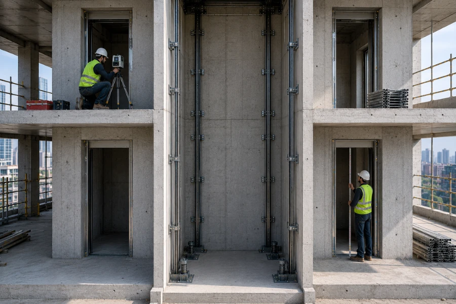
Why Small Shaft Errors Become Expensive Installation Problems
An elevator shaft connects the building structure with a precision mechanical system. A dimensional or structural error can therefore affect several downstream components.
| Early-Stage Error | Installation Effect | Project Consequence |
|---|---|---|
| Incorrect clear shaft size | Equipment clearance becomes insufficient | Structural modification |
| Insufficient pit depth | Bottom equipment conflicts | Pit modification or engineering review |
| Shaft out of plumb | Rail adjustment becomes difficult | Additional alignment work |
| Incorrect landing opening | Entrance alignment fails | Civil rework |
| Missing structural support | Brackets cannot be fixed as planned | Reinforcement or alternative fixing |
| Insufficient overhead | Upper equipment or clearances conflict | System-level review |
The earlier these conditions are identified, the more corrective options generally remain.
Mistake 1 — Treating Structural Dimensions as Clear Shaft Dimensions
Nominal structural dimensions do not necessarily represent the usable installation space inside an elevator shaft.
Wall thickness, beams, columns, finishes, and local projections can reduce the actual clear width or depth. A shaft that appears large enough on the general drawing may still contain a critical restriction at one elevation.
An undersized shaft is particularly restrictive because the car, counterweight, guide rails, doors, and required clearances must still fit within the remaining space.
Before structural dimensions are finalized, verify:
-
Clear shaft width and depth at multiple elevations
-
Beam and column projections
-
Elevator and entrance centerlines
-
Car and counterweight arrangement
-
Guide rail locations
-
Finished wall conditions
Shaft dimensions used for elevator coordination should represent the usable installation envelope rather than only the nominal structural opening.
Mistake 2 — Ignoring Verticality and Cumulative Construction Tolerance
A shaft can meet dimensional requirements at individual floors while gradually drifting from its intended centerline as the building rises.
Cumulative deviation can reduce the adjustment available for guide rail brackets and create uneven car or counterweight clearances. Differences between diagonal measurements can also indicate that the shaft is not truly rectangular.
This creates an important distinction:
Civil construction tolerance is not automatically elevator installation tolerance.
A deviation acceptable for general building work may consume space required by the elevator system. Its significance depends on shaft height, equipment arrangement, bracket design, and project requirements.
Verticality and shaft geometry should therefore be measured progressively during construction rather than checked only after the complete shaft has been built.
Mistake 3 — Getting Pit Depth and Pit Conditions Wrong
The pit provides space for buffers and other bottom-of-shaft equipment while contributing to the required elevator safety arrangement.
If the completed pit is too shallow, equipment or required clearances can conflict. One source of error is using the wrong elevation reference, particularly when structural levels and finished-floor levels are confused.
Pit condition also matters. Poor waterproofing or drainage can expose equipment to persistent moisture, increase corrosion risk, and make inspection more difficult.
Pit depth, waterproofing, and required drainage provisions should therefore be coordinated as one part of the shaft design.
Mistake 4 — Leaving Insufficient Overhead Space
Overhead errors can occur when teams check the nominal floor-to-slab dimension without identifying the lowest structural obstruction.
A beam projecting below the slab may become the actual limiting point. This can affect upper clearances, car-top equipment, guide rail arrangements, maintenance access, and machine-room-less equipment where applicable.
The complete three-dimensional top-of-shaft envelope should therefore be reviewed, including structural beams and other projections.
This becomes especially important when the elevator specification changes after structural design has progressed.
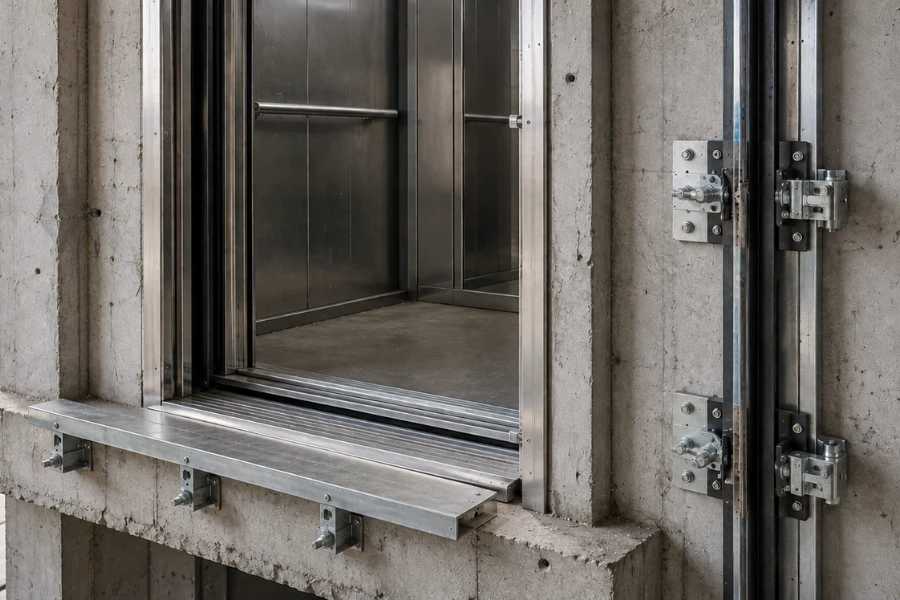
Mistake 5 — Misplacing Landing Door Openings
Landing openings must correspond with the selected door system at every floor.
Opening width and height are only part of the requirement. Centerline, sill position, and finished-floor elevation also affect entrance installation.
A correctly sized opening with the wrong centerline can still create the following sequence:
Incorrect Opening → Entrance Misalignment → Civil Modification → Installation Delay
Landing openings should therefore be checked floor by floor against the approved elevator layout before the surrounding construction becomes difficult to modify.
Mistake 6 — Providing Inadequate Guide Rail Fixing Conditions
Guide rails require reliable structural fixing points throughout the elevator travel.
Depending on shaft construction, the fixing arrangement may involve reinforced concrete, structural beams, ring beams, embedded steel, or another engineered solution. Problems occur when these provisions are missing, incorrectly positioned, or installed in substrates unsuitable for the required bracket arrangement.
Masonry shafts require particular attention to whether the wall construction can support the intended rail fixing system.
The practical verification question is:
Does the completed structure provide suitable load-bearing fixing conditions where the elevator layout requires them?
If not, reinforcement, alternative fixing arrangements, or structural modification may be required before guide rail installation.
Mistake 7 — Forgetting Installation Interfaces and Access
Correct shaft dimensions do not guarantee that the elevator can be installed efficiently.
Depending on the system and installation method, the project may also require:
-
Lifting provisions
-
Equipment openings
-
Electrical penetrations
-
Cable routes
-
Ventilation provisions
-
Temporary working arrangements
-
Equipment transportation access
Providing these interfaces after structural completion can require considerably more work than incorporating them during construction.
The intended installation method should therefore be considered before the shaft is handed over to the elevator contractor.
Mistake 8 — Coordinating the Elevator Too Late
Many shaft problems originate from elevator requirements being introduced after critical civil dimensions have already been fixed.
Architectural, structural, and elevator drawings serve different purposes. They need to be coordinated before construction proceeds.
Critical coordination points include:
-
Clear shaft dimensions
-
Pit and finished-floor elevations
-
Overhead conditions
-
Landing entrances
-
Structural projections
-
Guide rail fixing conditions
-
Lifting and installation provisions
-
Electrical interfaces
-
Machine-room or MRL conditions
A change in elevator capacity, car dimensions, door configuration, or equipment arrangement can make an earlier civil layout obsolete.
The latest elevator drawings should therefore remain synchronized with current architectural and structural information throughout the relevant design and construction stages.
How Elevator Shaft Errors Propagate Through a Project
The cost and disruption created by a shaft error depend partly on when it is discovered.
A drawing conflict identified during design may require only a drawing revision. The same conflict discovered after structural completion can develop into a longer sequence:
Drawing Mismatch → Civil Deviation → Reduced Installation Clearance → Equipment Conflict → Site Modification → Installation Delay → Inspection Risk → Maintenance Constraint
This propagation explains why relatively small dimensional or coordination errors can become expensive later in the project.
Shaft verification is therefore more effective as a staged process during design and construction than as a single inspection immediately before elevator installation.
When Can a Shaft Error Be Corrected and When Is Redesign Needed?
Not every shaft deviation requires reconstruction, but site adjustment should not be treated as the automatic solution.
| Shaft Condition | Potential Engineering Response |
|---|---|
| Minor dimensional deviation | Layout or bracket adjustment may be possible |
| Local obstruction | Engineering review and localized modification |
| Incorrect landing opening | Entrance modification |
| Missing fixing condition | Reinforcement or alternative fixing design |
| Water entering the pit | Waterproofing and drainage correction |
| Insufficient pit or overhead | Structural and elevator engineering review |
| Major incompatibility | Civil redesign or elevator configuration change |
The appropriate response depends on the magnitude and location of the deviation, structural conditions, elevator configuration, and applicable requirements.
Changes affecting structural capacity, equipment clearance, or safety space should receive engineering review rather than improvised site correction.
Elevator Shaft Pre-Installation Verification Checklist
Before elevator installation, a coordinated shaft survey should verify:
-
Clear width and depth at multiple levels
-
Shaft verticality and diagonal geometry
-
Pit depth and condition
-
Waterproofing and drainage provisions
-
Overhead clearance
-
Structural beam projections
-
Landing opening dimensions and centerlines
-
Finished-floor elevations
-
Guide rail fixing conditions
-
Structural and embedded provisions
-
Lifting requirements
-
Electrical and cable penetrations
-
Equipment transportation and installation access
-
Consistency between civil and elevator drawings
Any deviation should be documented and reviewed before equipment installation. Corrective options generally become more limited after guide rails, entrances, or machinery are installed.
How Better Project Coordination Reduces Shaft Rework
Effective coordination starts before critical shaft dimensions and structural interfaces become permanent.
This is particularly important for international projects where elevator manufacturing and building construction may proceed in different locations. Measurement references, drawing revisions, structural changes, and equipment specifications need to remain synchronized.
EKCNE approaches elevator projects around building compatibility. Shaft conditions, capacity, travel, door arrangement, installation environment, structural interfaces, and equipment configuration can be reviewed during project planning and manufacturing coordination.
The objective is to identify dimensional and interface conflicts while they can still be resolved through engineering decisions rather than later site modification.
Final Takeaway
The most consequential elevator shaft problems usually involve the interface between civil construction and the elevator system rather than one isolated dimensional error.
Clear shaft dimensions, verticality, pit conditions, overhead space, landing openings, structural fixing points, and installation access all need to correspond with the approved elevator configuration.
Verifying these conditions progressively during design and construction provides more corrective options than discovering the same incompatibilities immediately before installation.