Introduction
Adding an elevator to an existing building can be constrained by the absence of reserved shaft space, limited structural capacity, or the amount of modification the existing building can tolerate.
A self supporting elevator shaft addresses these constraints through an independent structural frame. Instead of relying primarily on existing walls or the main building structure, the shaft transfers its primary structural loads through its own frame and foundation.
This configuration is commonly considered for existing-building retrofits, villas, external elevators, and projects where structural modification or onsite disruption needs to be limited. Its feasibility still depends on foundation conditions, elevator dimensions, installation access, environmental loads, and maintenance requirements.
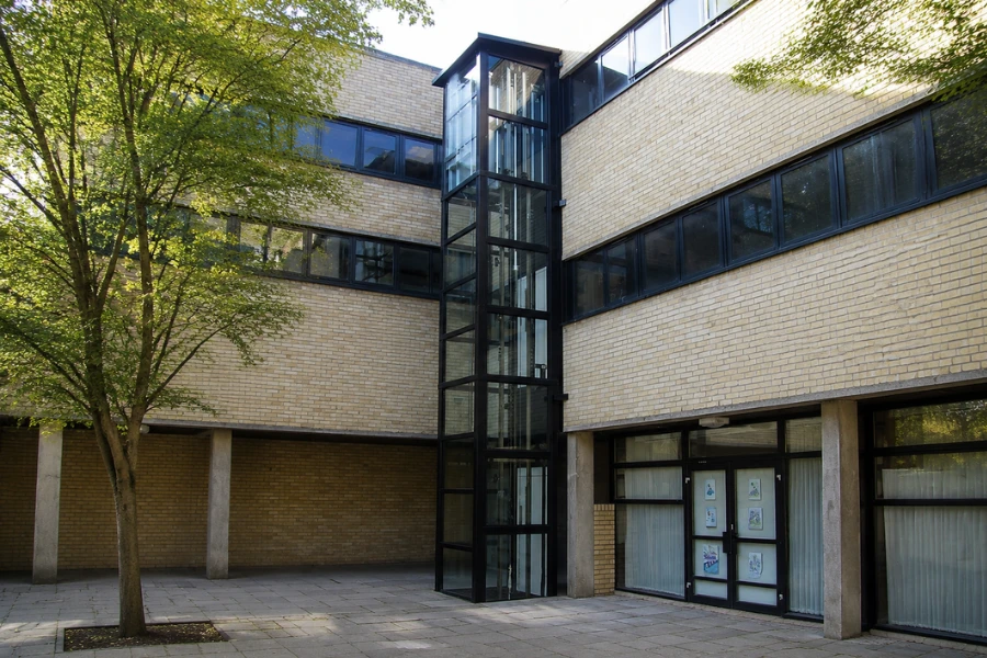
What Is a Self Supporting Elevator Shaft?
A self supporting elevator shaft has its own primary load-bearing structure rather than depending on the existing building to support the elevator installation.
The engineering distinction is primarily the load path.
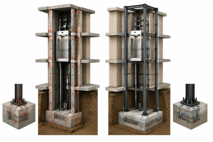
Traditional integrated shaft
Building structure
↓
Elevator shaft
↓
Elevator system
Self supporting shaft
Independent shaft structure
↓
Foundation system
↓
Elevator system
“Self supporting” does not mean foundation-free or completely disconnected from the building. Connections may still be required for lateral restraint, landing interfaces, enclosure integration, or other project requirements.
The distinction is that the shaft’s primary structural support comes from its dedicated frame and foundation rather than existing walls.
How the Independent Shaft Structure Works
Load Transfer and Structural Stability
An elevator installation creates loads from the shaft structure, elevator equipment, cabin and passengers, guide rail reactions, and dynamic operation. External shafts must also resist environmental loads.
Vertical columns transfer primary loads toward the foundation, while horizontal members and structural connections provide stiffness and maintain the geometry required for elevator operation.
Depending on the project, the structural frame may use steel, aluminum, or another engineered system. Steel can provide high strength and fabrication flexibility, while aluminum may be considered where lower structural weight or architectural requirements affect material selection.
For an external installation, the structural design must additionally account for wind exposure, weather, corrosion protection, drainage, and connection durability.
The resulting independent load path can provide more freedom in shaft placement, including locations beside an exterior wall, within a courtyard, or in another area not originally designed for an elevator.
Prefabricated and Modular Construction
Many self supporting shafts use prefabricated structural components rather than completing all fabrication onsite.
A typical sequence is:
-
Site measurement and building evaluation
-
Elevator and shaft configuration
-
Structural design
-
Factory fabrication
-
Transportation
-
Site assembly
-
Elevator installation and commissioning
Moving fabrication away from the building reduces the amount of cutting, welding, and structural assembly required onsite.
For occupied properties, this can reduce interference with residents or building operations and make the onsite construction schedule more predictable.
Where Self Supporting Elevator Shafts Are Used
Existing Building Retrofits
Older residential buildings, public facilities, and commercial properties may have no reserved elevator space. Creating a conventional integrated shaft can require changes to slabs, walls, circulation areas, or other parts of the original structure.
An independent shaft can reduce reliance on these structural elements and make an external or adjacent elevator possible.
Potential advantages include:
-
Less dependence on existing load-bearing elements
-
Reduced internal demolition
-
Greater flexibility in shaft location
-
Compatibility with prefabricated construction
-
Less disruption inside occupied spaces
The critical retrofit interfaces are usually the foundation, landing connections, shaft dimensions, elevator configuration, and installation access. These need to be resolved as one system rather than treating the shaft as a separate structural enclosure.
Villas and Home Elevators
Existing villas and private residences often have limited space for an elevator. Preserving rooms and circulation space can make an external or courtyard installation more practical than constructing a new internal shaft.
The shaft configuration needs to match:
-
Elevator capacity
-
Travel height
-
Cabin dimensions
-
Door arrangement
-
Drive system
-
Noise requirements
-
Maintenance access
Hydraulic, traction, and screw-driven home elevators have different dimensional and operating requirements. The elevator technology therefore influences the shaft rather than being selected independently after the enclosure is designed.
External and Panoramic Elevators
Self supporting structures can also be used for external elevators where architectural integration is part of the project.
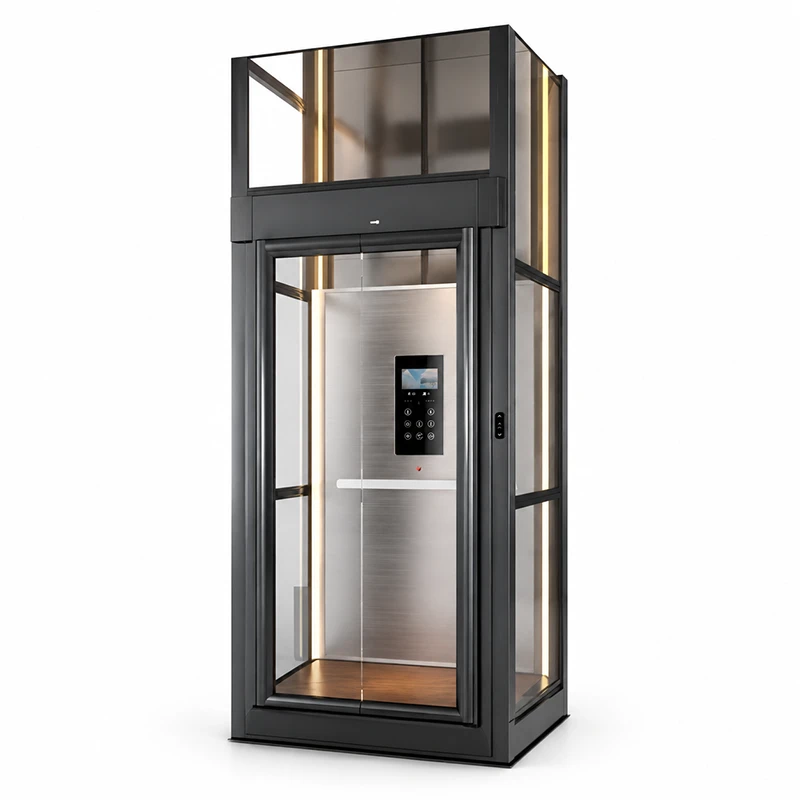
Panoramic systems may use glass cabins or transparent enclosures in hotels, commercial properties, public facilities, and accessibility upgrades.
These applications add requirements beyond basic structural support:
-
Outdoor structural stability
-
Compatibility with glazing systems
-
Weather protection
-
Corrosion resistance
-
Drainage
-
Maintenance and cleaning access
An external shaft has greater environmental exposure than an indoor shaft. Wind, rainwater, temperature variation, humidity, and material durability therefore become direct design variables.
Key Engineering Factors Before Selecting a Self Supporting Shaft
A self supporting structure provides greater independence from the existing building, but that does not make it suitable for every project.
Foundation and Structural Stability
Structural independence transfers more responsibility to the shaft’s own foundation.
The foundation may need to resist loads associated with:
-
Shaft self-weight
-
Elevator equipment
-
Cabin and passengers
-
Dynamic operation
-
Environmental exposure
Ground conditions, shaft height, load path, installation location, and applicable construction requirements therefore need to be evaluated before the structural system is finalized.
Foundation movement can affect more than the shaft frame. Settlement or structural displacement can alter guide rail geometry and elevator leveling, creating operational and maintenance problems.
The purpose of a self supporting system is to reduce dependence on the existing building, not to eliminate structural engineering.
Shaft Dimensions and Elevator Compatibility
The shaft dimensions need to follow the elevator configuration.
Coordination includes:
-
Cabin dimensions
-
Door opening
-
Pit depth
-
Overhead clearance
-
Travel distance
-
Rated capacity
-
Drive system requirements
-
Maintenance space
Some existing-building applications may use elevator capacities around 450–1,000 kg and operating speeds around 1.0–1.5 m/s, depending on project requirements and local standards.
These figures are not universal limits for self supporting shafts. Building use, passenger demand, elevator type, available dimensions, and regulatory requirements determine the final specification.
Environmental Loads
Outdoor shafts must resist conditions that indoor elevator shafts are largely protected from by the building envelope.
Relevant variables include:
-
Wind pressure
-
Rainwater
-
Temperature variation
-
Humidity
-
Corrosion exposure
Wind becomes particularly important as shaft height increases because excessive structural movement can affect guide rail alignment, ride behavior, and elevator operation.
Structural stiffness, connection durability, surface protection, drainage, and enclosure weather resistance therefore need to be considered together.
Maintenance and Modernization Access
Reducing shaft dimensions can solve an installation-space problem while creating a future service problem.
The design should provide sufficient access for:
-
Routine inspections
-
Safety checks
-
Component replacement
-
Major equipment removal
-
Future modernization
Replacement paths and working clearances are especially important in compact retrofit installations. Equipment that can be installed during initial construction may be difficult to remove later if surrounding access becomes restricted.
Self Supporting vs. Traditional Elevator Shafts
The two systems differ primarily in structural integration and project context.
| Factor | Self Supporting Shaft | Traditional Shaft |
|---|---|---|
| Primary structural support | Dedicated shaft structure and foundation | Integrated with main building structure |
| Typical project stage | Retrofit or later addition | Planned during original construction |
| Existing-building modification | Can reduce structural modification | May require substantial modification when retrofitted |
| Location flexibility | Greater flexibility for external or constrained sites | More dependent on original building layout |
| Onsite construction | Can use prefabricated assembly | Often more closely integrated with building construction |
| Structural coordination | Independent foundation and building interfaces | Coordinated with overall building structure |
Neither configuration is inherently preferable.
An integrated reinforced concrete shaft can be practical for new buildings where the elevator core is designed together with the primary structure, fire strategy, and circulation system.
A self supporting shaft becomes more relevant when the building already exists, available internal space is limited, or reducing structural modification is a project priority.
When a Self Supporting Shaft May Not Be Appropriate
A conventional integrated shaft may be more practical when:
-
A new building already includes a dedicated elevator core
-
Reinforced concrete shaft space is incorporated into the structural design
-
Local requirements favor an integrated structural solution
-
A very tall building requires extensive integration with the primary structure
-
Elevator, fire protection, and other building systems are already coordinated around a conventional core
The purpose of a self supporting system is therefore not to replace conventional shafts. It provides another structural strategy where retrofit flexibility and reduced dependence on the original structure have greater value.
Common Project Risks
Foundation Movement
The most important structural risk can be represented as a failure chain:
Insufficient foundation assessment
↓
Settlement or structural movement
↓
Guide rail geometry changes
↓
Leveling or ride-performance problems
↓
Additional adjustment and maintenance
Foundation design therefore needs to reflect ground conditions, shaft height, elevator loads, and environmental loads rather than the shaft’s self-weight alone.
Shaft and Elevator Interface Errors
Designing the structural enclosure separately from the elevator can create:
-
Incorrect shaft dimensions
-
Insufficient pit or overhead clearance
-
Misaligned landing positions
-
Inadequate maintenance space
-
Incompatible equipment arrangements
These conflicts are most expensive when discovered after structural fabrication.
Elevator specifications, shaft dimensions, landing interfaces, installation sequence, and maintenance requirements should therefore be coordinated before manufacturing begins.
External Exposure
For outdoor shafts, failures can also occur at the enclosure rather than the primary frame.
Poor drainage, inadequate sealing, corrosion protection failures, or unsuitable connections can expose the structure and elevator equipment to moisture and long-term deterioration.
Environmental protection should therefore be resolved during structural and enclosure design rather than treated as a finishing detail.
Maintenance Constraints
A compact shaft can pass initial installation requirements but still create lifecycle problems if inspection and replacement access is insufficient.
This risk is particularly important where space has been reduced to accommodate an elevator within an existing property.
The design should account for both routine service and future removal or replacement of major components.
Self Supporting Elevator Shaft Project Workflow
1. Site Evaluation
The project begins by establishing the constraints that the shaft and elevator must fit.
The assessment should cover:
-
Available installation area
-
Existing structural limitations
-
Passenger and usage requirements
-
Construction access
-
Proposed landing locations
-
Ground and foundation conditions
-
Local approval requirements
-
Environmental exposure for external installations
Actual site measurements are particularly important in retrofit work because existing drawings may not fully represent current building conditions.
2. Elevator and Shaft Configuration
The elevator requirements are coordinated with the available building envelope.
Key variables include:
-
Elevator type
-
Rated capacity
-
Travel height
-
Number of stops
-
Cabin dimensions
-
Door arrangement
-
Drive system
-
Pit and overhead requirements
-
Maintenance access
These inputs establish the dimensional and structural requirements for the shaft.
3. Structural and Foundation Design
Once the elevator configuration is defined, the structural system can be developed around its loads and required geometry.
This stage determines:
-
Structural members
-
Foundation requirements
-
Building connections
-
Lateral stability
-
Environmental loads
-
Enclosure interfaces
-
Installation tolerances
The foundation and shaft frame should be treated as one load-transfer system.
4. Factory Fabrication and Logistics
Prefabricated systems allow structural components to be produced under controlled manufacturing conditions before site assembly.
Factory production can improve control over:
-
Structural dimensions
-
Component consistency
-
Manufacturing sequence
-
Inspection before shipment
For international projects, module dimensions also need to account for packaging, container or transport limitations, site access, and available lifting equipment.
Prefabrication only reduces onsite complexity when the fabricated components can actually be transported to and assembled at the installation location.
5. Site Assembly
Typical site work includes:
-
Foundation preparation
-
Component delivery
-
Structural frame erection
-
Connection inspection
-
Enclosure installation
-
Building interface work
Structural tolerances need to remain compatible with the elevator’s guide rail, landing, and equipment requirements.
6. Elevator Installation and Commissioning
After the shaft reaches the required structural condition, elevator installation can proceed.
Typical activities include:
-
Guide rail installation
-
Elevator equipment installation
-
Landing door integration
-
Electrical connections
-
Safety system testing
-
Operating adjustments
-
Final inspection
Commissioning verifies that the structural shaft and elevator equipment function as a coordinated vertical transportation system.
How EKCNE Supports Self Supporting Elevator Shaft Projects
A self supporting elevator project involves interfaces between the building, foundation, shaft structure, elevator equipment, logistics, and installation team.
EKCNE supports international projects through elevator systems, shaft configurations, customized manufacturing coordination, and export delivery support.
Project evaluation can include:
-
Building compatibility
-
Traffic requirements
-
Shaft conditions
-
Installation limitations
-
Maintenance accessibility
-
Long-term supply requirements
Coordinating the shaft and elevator within the same project framework can reduce dimensional and installation conflicts between separately specified systems.
For international projects, this coordination also extends to manufacturing, packaging, transportation, and installation requirements that need to be established before equipment reaches the site.
Conclusion
A self supporting elevator shaft provides an independent structural approach for elevator projects where relying on the existing building structure or constructing a conventional integrated shaft is impractical.
Its main engineering advantage is the independent load path, but that advantage depends on a properly designed foundation, compatible elevator dimensions, adequate structural stiffness, suitable environmental protection, and sufficient maintenance access.
For retrofit, villa, and external elevator projects, evaluating these conditions before structural fabrication helps determine whether a self supporting shaft is appropriate and prevents installation constraints from becoming long-term operational problems.