An elevator control system is more than a controller cabinet that tells the car when to move. It is an interconnected architecture coordinating passenger requests, operating logic, motor control, door operation, position feedback, safety conditions, and communication across the elevator.
For project teams, this architecture affects ride performance, wiring complexity, traffic handling, fault diagnosis, maintenance, and future modernization. The appropriate configuration depends on the building, elevator arrangement, number of stops, operating requirements, and long-term service strategy.
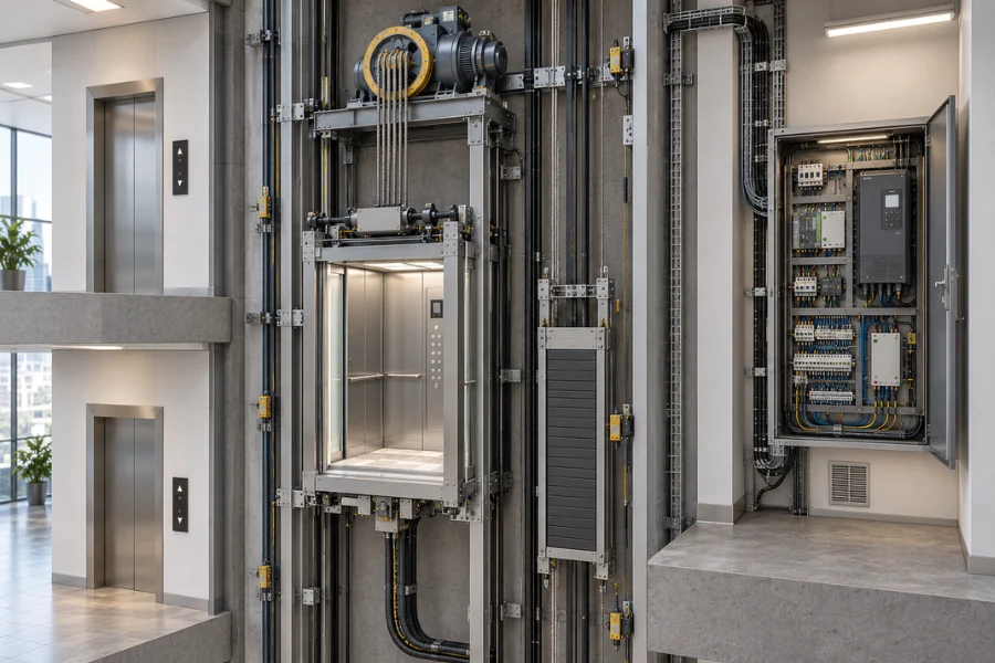
How an Elevator Control System Is Structured
At a functional level, elevator control architecture can be divided into connected layers. Passenger and field inputs provide operating information, the controller makes decisions, the drive regulates motion, and feedback devices report actual conditions.
A simplified control sequence is:
Passenger and field inputs → Logic control → Motion control → Motor and brake → Elevator movement → Feedback
Door control, safety circuits, and communication networks operate alongside this sequence. Multi-elevator installations add another layer for traffic coordination.
| Architecture Layer | Main Function | Typical Elements |
|---|---|---|
| Input and sensing | Collect requests and operating conditions | Hall calls, car buttons, position sensors, door signals |
| Logic control | Determine elevator operation | PLC, microprocessor, main controller |
| Motion control | Regulate speed, torque, and stopping | VVVF drive, motion control functions |
| Execution | Perform physical movement | Traction motor, brake, door operator |
| Feedback | Report speed and position | Encoder, leveling and position sensors |
| Safety | Verify safe operating conditions | Door interlocks, safety circuit, terminal protection |
| Communication | Exchange system information | Serial networks, CAN, I/O modules |
| Traffic coordination | Coordinate multiple cars | Group controller, dispatching logic |
Separating these functions conceptually helps project teams understand system configuration, interface requirements, and fault diagnosis.
Logic Control and Elevator Operating Decisions
The logic controller determines what the elevator should do based on passenger demand and current operating conditions.
It receives car calls, hall calls, position information, travel direction, door status, operating mode, and relevant safety conditions. Based on these inputs, the controller determines whether the elevator should run, where it should stop, and when the doors should operate.
A typical operating sequence can be simplified as:
Call registration → Direction selection → Door closing → Run permission → Acceleration → Travel → Deceleration → Leveling → Door opening
Older elevators implemented much of this logic through interconnected relays and contactors. PLC and microprocessor control moved much of the logic into programmable processing, allowing more functions without increasingly complex relay circuits.
During modernization, replacing the controller is therefore not simply a cabinet change. Existing landing signals, door equipment, position feedback, drive equipment, and safety interfaces must remain compatible with the new control arrangement.
Drive and Motion Control Architecture
Logic control determines where and when the elevator should move. Motion control determines how that movement occurs.
In a modern traction elevator, the basic relationship can be represented as:
Main controller → VVVF drive → Traction motor → Car movement
A variable voltage variable frequency drive regulates the motor supply so speed and torque can be controlled during starting, acceleration, travel, deceleration, and stopping.
Feedback closes the control loop:
Motor and car movement → Encoder feedback → Drive and controller
The encoder provides speed and position information that supports controlled motion and accurate leveling. Motor type, rated speed, travel, encoder configuration, drive compatibility, and control strategy therefore need to be considered together.
A low-rise residential elevator and a faster commercial elevator with more stops and heavier traffic may require different control and drive configurations even though their basic architecture is similar.
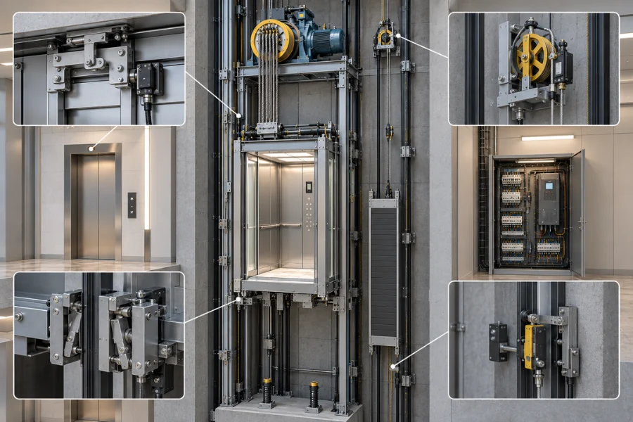
Input, Output, Sensors, and Field Devices
The controller depends on devices distributed throughout the car, hoistway, and landings to determine what is happening in the system.
Passenger and Landing Inputs
Car operating panels register floor selections and commands such as door opening or closing. Hall call stations provide demand signals from individual floors.
These inputs tell the controller where transportation demand exists so it can respond according to the configured operating strategy.
Position and Motion Feedback
The control system must know where the car is and how it is moving.
Depending on the design, feedback may involve rotary encoders, leveling sensors, floor-position signals, and terminal devices. These signals support deceleration, stopping, leveling, and position monitoring.
Control Outputs
After processing inputs, the controller sends commands to the drive, brake, door operator, floor indicators, direction displays, and other controlled devices.
The elevator therefore operates through a continuous cycle of sensing, decision-making, execution, and feedback, rather than through the controller alone.
Door Control and Safety Circuits
Door operation is integrated with normal elevator control, while safety-related functions require separate consideration.
Door Control
The door system coordinates opening, closing, speed adjustment, and door-position detection. Modern controlled door operators can provide smoother movement than older resistance-based arrangements.
The main controller coordinates door operation with floor arrival and passenger demand. Door status also determines whether normal elevator movement can begin.
Safety Circuit
The safety chain should not be treated as another set of normal software commands.
Safety devices and interlocks prevent or interrupt operation when required conditions are not satisfied. Depending on the system, these may include door interlocks, emergency stop devices, terminal protection, overspeed protection, and other safety-related devices.
Normal logic may request elevator movement, but the system should not be permitted to run unless the required safety conditions are established. This distinction between an operating command and permission to operate safely is fundamental to the control architecture.
Communication Architecture and Distributed Control
Traditional systems relied heavily on individual wires connecting field devices directly to a central controller. As the number of floors and functions increased, point-to-point wiring also became more extensive.
Serial communication allows controllers and intelligent devices to exchange information through shared networks. A distributed architecture may include a main controller, car control modules, landing nodes, I/O modules, and communication interfaces.
A simplified arrangement is:
Main controller ↔ Car control module ↔ Landing nodes ↔ Field I/O
CAN and other serial communication methods can reduce wiring and organize distributed devices more systematically. Modular communication can also support system expansion and structured fault diagnostics.
The trade-off is greater dependence on communication integrity and component compatibility. Network configuration, replacement modules, and diagnostic capability therefore become part of long-term maintenance planning.
From Relay Control to Integrated Elevator Controllers
Elevator control architecture has evolved as buildings and operating requirements have become more complex.
Early relay systems implemented logic through physical wiring. PLC and microprocessor systems moved much of this logic into programmable controllers, while serial communication reduced dependence on extensive point-to-point connections.
More integrated platforms can coordinate elevator logic and drive functions within the same control system.
| Architecture | Main Characteristic | Project Consideration |
|---|---|---|
| Relay control | Hardwired operating logic | High wiring and maintenance complexity |
| PLC control | Programmable logic | Flexible and mature control approach |
| Microprocessor control | Higher integration and expanded functions | Hardware and software compatibility |
| Distributed control | Networked controllers and I/O nodes | Less wiring but greater communication dependency |
| Integrated control | Coordinated logic and drive functions | Compact design with stronger platform dependency |
Newer technology is not automatically more suitable. A highly integrated controller may simplify equipment and connections, while a more modular architecture can provide different maintenance and replacement options.
The control platform should therefore be evaluated against project requirements rather than controller generation alone.
Single-Elevator Control vs. Group Control Architecture
A single elevator controller primarily manages one car. Once several elevators share passenger demand, traffic becomes a system-level control problem.
A simplified group architecture is:
Passenger demand → Group control → Car assignment → Individual elevator controller → Motion control
The group controller evaluates demand and assigns calls among available cars. Individual controllers remain responsible for operating their assigned elevators.
This distinction becomes important in office towers, hotels, hospitals, and mixed-use buildings because traffic is rarely distributed evenly throughout the day. Office buildings can experience concentrated up-peak traffic, while hotels and hospitals may have more varied passenger and service movements.
Control architecture is therefore closely connected to traffic planning.
How Control Architecture Affects Elevator Projects
Building height, number of stops, elevator quantity, traffic patterns, and equipment layout all influence control requirements.
More stops increase the number of landing devices and signals that must be managed. Multi-car installations add traffic coordination, while different building uses can require inspection, fire-related, priority, access-management, or other special operating modes.
Machine-room and machine-room-less layouts also affect controller location, wiring routes, equipment access, and maintenance conditions. MRL is not a separate control technology by itself. It is an equipment layout that creates specific integration requirements for the controller, drive, traction machine, and service access.
Control architecture should therefore be considered during elevator and building coordination rather than selected independently after the main equipment arrangement has already been defined.
Maintenance and Modernization Depend on Architecture
Control architecture continues to influence the elevator after commissioning.
Modern diagnostic functions can simplify fault identification, but maintenance teams still need access to compatible controllers, drives, communication modules, and service tools. Greater integration can reduce hardware complexity while increasing dependence on a particular control platform.
Modernization requires a broader compatibility review. A replacement controller must be considered together with the existing drive, encoder, door operator, communication devices, safety interfaces, and wiring.
Keeping some existing equipment may reduce project scope, but only when the interfaces remain technically compatible. Spare-parts continuity and future replacement options should therefore be considered when the original control system is selected.
How to Evaluate an Elevator Control System
Controller brand or processor specifications alone do not determine whether a control system fits a project.
Project teams should evaluate:
-
What are the building height, travel, and number of stops?
-
What rated load and operating speed are required?
-
Will the installation operate as a single elevator or a multi-car group?
-
What motor, drive, encoder, and leveling configuration will be used?
-
How are car, landing, and field devices connected?
-
What communication architecture and diagnostic functions are provided?
-
Which special operating modes are required?
-
How accessible are the control and drive equipment for maintenance?
-
Are replacement components and technical support available over the expected service life?
-
Can the architecture support practical future modernization?
These questions connect control technology with building operation, installation, maintenance, and lifecycle planning.
For project-oriented elevator procurement, evaluating overall system compatibility is generally more useful than comparing controllers through isolated specifications.
Building the Right Control Architecture for the Project
Elevator control system architecture should be viewed as a coordinated relationship among logic, motion, feedback, safety, communication, and building transportation requirements.
Greater controller sophistication does not automatically produce a more suitable project configuration. The more important question is whether the architecture fits the building height, number of elevators, traffic pattern, drive configuration, installation conditions, maintenance strategy, and future modernization requirements.
For new installations, OEM projects, and modernization work, EKCNE evaluates control configuration as part of the complete vertical transportation system. Considering these relationships early helps project teams develop an elevator solution that supports immediate building requirements and long-term operation.