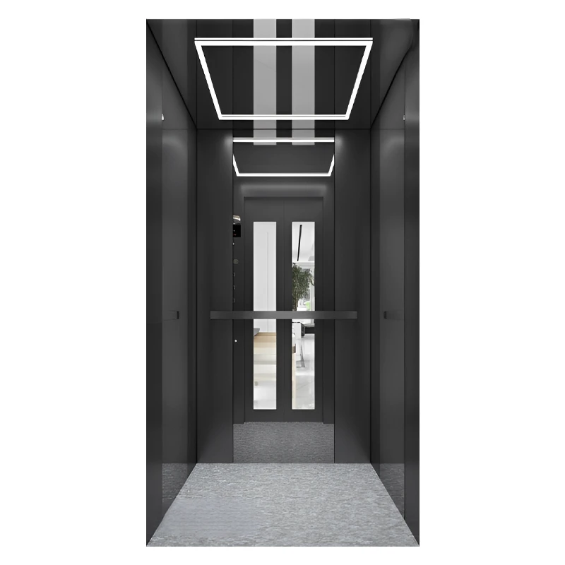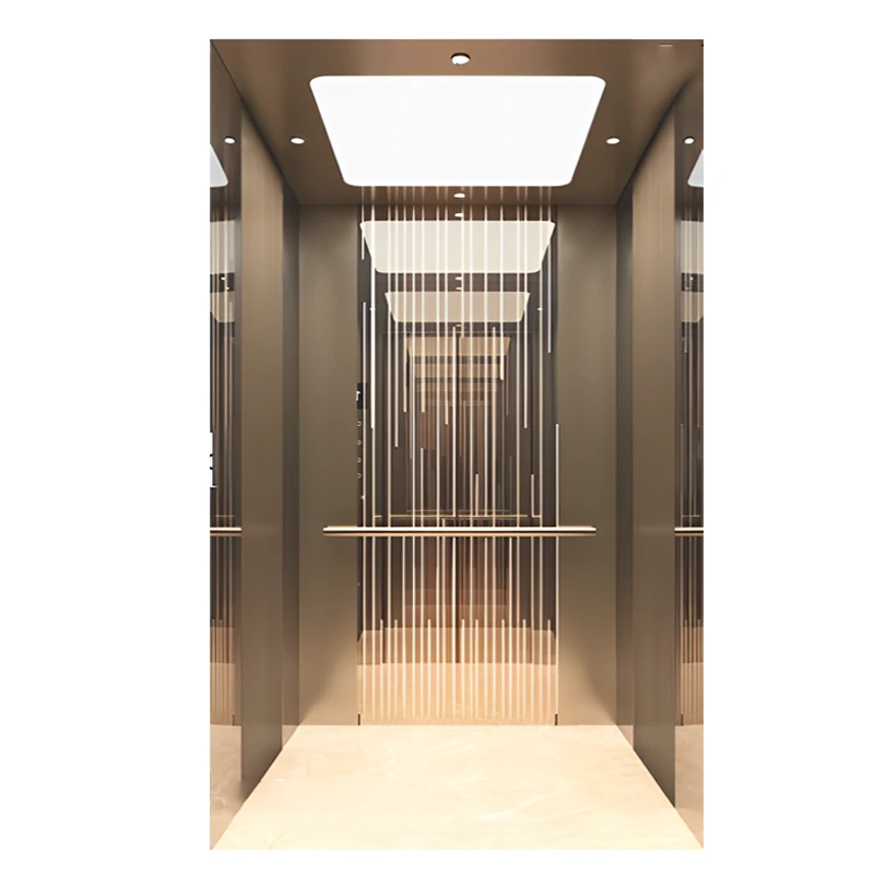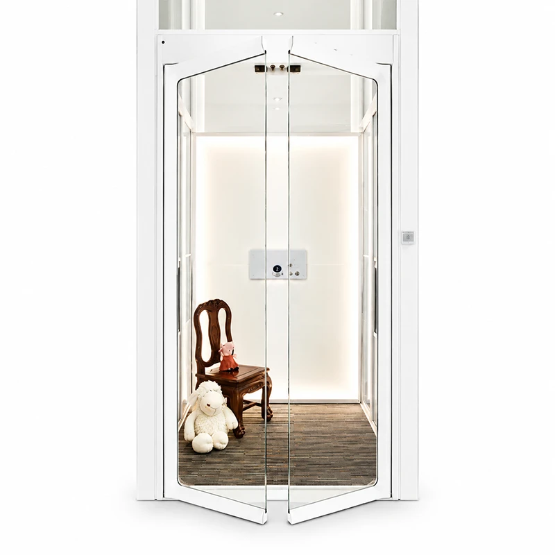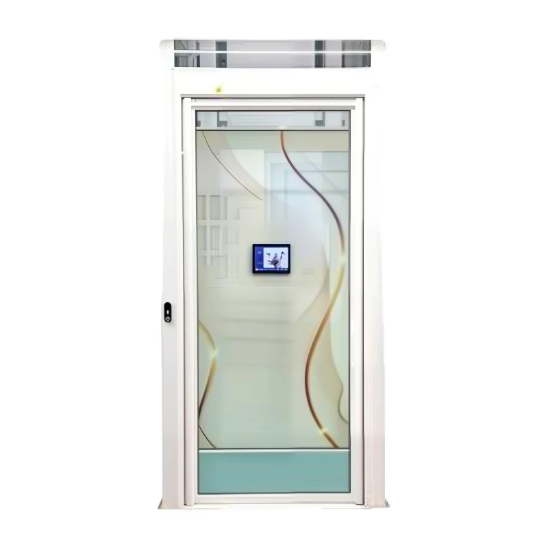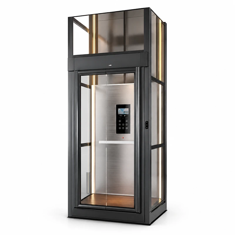
Elevator overhead is the vertical space above the highest landing required for the car, car-top equipment, terminal movement and applicable safety clearances. The required dimension varies with car geometry, rated speed, drive arrangement, structural obstructions and the safety requirements governing the project.
There is no universal minimum overhead for every elevator. Published manufacturer dimensions can support preliminary planning, but final construction dimensions must match the selected elevator configuration and project layout.
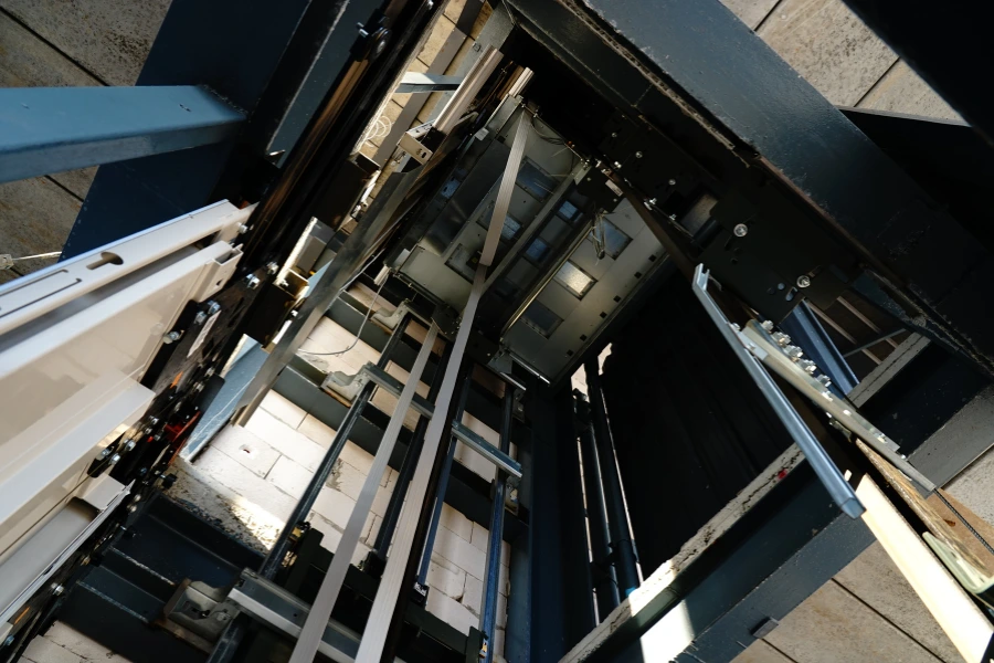
What Is Elevator Overhead?
Elevator overhead, sometimes described as hoistway overhead or shaft headroom in project documentation, refers to the vertical space above the highest landing reserved for the elevator system.
It is generally measured from the highest landing’s finished floor level to the underside of the controlling overhead obstruction. The exact datum must follow the selected elevator’s layout documentation.
The controlling obstruction may be the roof slab, a structural beam, a hoist beam or another permanent component extending into the shaft. If a roof slab is 4,500 mm above the top landing but a beam projects 300 mm below it, the available clear overhead beneath that beam is 4,200 mm.
Overhead vs. Top Clearance
Overhead, top clearance, run-by and overtravel describe related but different dimensions or conditions.
| Term | Meaning | Project Relevance |
|---|---|---|
| Overhead height | Vertical distance from the top landing to the controlling overhead obstruction | Defines available shaft-head space |
| Top clearance | Required free space between relevant elevator components and overhead structures under specified conditions | Supports terminal safety requirements |
| Run-by | A code-defined terminal travel allowance associated with the car or counterweight beyond its normal terminal position | Affects terminal movement and clearance evaluation |
| Overtravel | Movement beyond the normal terminal stopping position | Must be considered in terminal protection design |
| Car-top safety space | Protected space or clearance for personnel under defined terminal conditions | Helps protect personnel from crushing hazards |
The exact reference conditions for these terms depend on the elevator configuration and applicable code. Available architectural overhead therefore cannot by itself establish whether a particular elevator satisfies its required terminal clearances.
What Determines Elevator Overhead Requirements?
Required overhead depends on the physical elevator arrangement and the terminal conditions defined for that system.
1. Elevator Car and Cab Height
Interior cab height is only part of the vertical car envelope. Space may also be occupied by:
- Car frame and crosshead
- Cab roof structure
- Door operator equipment
- Car-top inspection equipment
- Guardrails and protective components
- Equipment or structural projections above the cab
Increasing the interior height of a hotel elevator, for example, can change the car frame or position of equipment above the cab. A taller architectural cab can therefore require additional overhead even when rated capacity remains unchanged.
Manufacturer planning data may specify additional overhead for taller cars within particular configurations. The adjustment is model-specific and should not be converted into a universal height-to-overhead rule.
2. Rated Elevator Speed
Rated speed can affect overhead through the terminal conditions that must be accommodated beyond normal floor-level operation.
As speed increases, stopping-distance-related allowances, buffer arrangements or other terminal conditions may change. Depending on the elevator design and applicable code, these changes can increase the required vertical safety envelope.
Published Schumacher planning data for selected MRL traction configurations with an 8-foot cab illustrates this relationship.
| Rated Speed | Published Planning Example |
|---|---|
| Up to 200 fpm | 17 ft |
| 350 fpm | 17 ft 6 in |
| 400 fpm | 17 ft 9 in |
| 500 fpm | 18 ft 6 in |
These values apply to the stated manufacturer configurations and are not universal code minimums.
Speed does not translate into a fixed amount of additional overhead. Suspension arrangement, buffer characteristics, drive design and terminal protection can change how the vertical safety envelope is established.
3. Run-By and Terminal Travel
The normal stopping position at the highest landing is not the limiting position used for every overhead clearance check.
Run-by is a code-defined terminal travel allowance associated with the car or counterweight beyond its normal terminal position. Its datum and limiting condition depend on the elevator configuration and applicable standard.
In traction systems, car movement, counterweight movement and buffer conditions can affect terminal clearances. Measuring the space above a car parked normally at the highest landing therefore does not by itself establish compliance.
4. Car-Top Safety Space and Clearance
Maintenance personnel may need access to the car top for inspection, adjustment and servicing. Elevator standards therefore establish protected-space or clearance requirements under defined terminal conditions.
Depending on the code and edition, these requirements may be expressed through refuge-space provisions, top-of-car clearances or related protected-space criteria. Evaluation can involve:
- Maximum upward movement under the applicable terminal condition
- Remaining clearance to the lowest obstruction
- Car-top equipment projections
- Structural projections
- Space available for personnel under defined conditions
The relevant safety condition can be understood as:
Normal top landing position → maximum upward movement under the applicable terminal condition → remaining clearance to the lowest obstruction
Terminal stopping and overspeed protection do not replace required physical clearances. They form different parts of the terminal safety system.
5. Drive System and Machine Arrangement
Hydraulic, conventional traction and MRL elevators place machinery and supporting equipment differently.
The resulting overhead depends on where the machine, supports, suspension components and maintenance-access provisions are located. Elevator type alone is therefore insufficient to determine the required shaft-head dimension.
6. Structural Obstructions
Roof slabs do not always determine usable overhead. Reinforced concrete beams, steel framing, hoist beams and equipment supports can create a lower controlling obstruction.
Hoist beams require particular coordination because their effect depends on the final arrangement. A temporary installation component does not create the same permanent clearance condition as a beam or support that remains within the shaft head.
Typical Elevator Overhead Dimensions
Published dimensions vary substantially between elevator configurations. The examples below illustrate that variation and should be treated as published planning examples, not universal code minimums.
| Elevator Configuration | Published Planning Example | Example Conditions |
|---|---|---|
| Compact residential hydraulic elevator | 96 in (2,438 mm) | Selected Federal Elevator residential configuration |
| Commercial LULA elevator | 11 ft 2 in (3,404 mm) | Selected Federal Elevator Serenus LULA configuration |
| Commercial MRL traction elevator | 17 ft (5,182 mm) | Selected Schumacher configuration at up to 200 fpm |
| Commercial MRL traction elevator | 18 ft 6 in (5,639 mm) | Selected Schumacher configuration at 500 fpm |
The difference between these values reflects differences in car geometry, speed, suspension, machinery location and applicable safety provisions. Even within one product category, changing the car height, speed or mechanical arrangement can change the required overhead.
Why Rated Load Alone Cannot Determine Overhead
Rated load is an input to elevator selection, not an overhead lookup key.
Two elevators with the same rated load can use different car dimensions, speeds, counterweight arrangements and drive systems. Overhead must therefore be determined from the complete configuration rather than capacity alone.
Does an MRL Elevator Require Less Overhead?
Not necessarily. Removing the conventional machine room changes where machinery is located, but it does not remove the traction machine, structural supports, terminal clearances or maintenance-access requirements.
| Design Consideration | Machine-Room Elevator | MRL Elevator |
|---|---|---|
| Main machine location | Separate machinery room | Hoistway or designated machinery space |
| Shaft-head equipment | Depends on suspension and system arrangement | May include machine and associated supports |
| Maintenance access | Includes dedicated machinery-room access | Depends on integrated equipment arrangement |
| Overhead requirement | Configuration-dependent | Configuration-dependent |
| Main planning issue | Space for dedicated machinery room | Machine, support and access integration within the building |
An MRL configuration can reduce the building area allocated to a conventional machine room without reducing clear overhead. Meaningful comparison therefore requires equivalent capacity, speed, car height and project conditions.
How Elevator Codes Affect Overhead Requirements
The applicable safety framework depends on project jurisdiction and can affect how terminal movement, clearances and protected spaces are defined.
Common frameworks include:
| Standard | Application Context |
|---|---|
| ASME A17.1 / CSA B44 | Elevator and escalator safety requirements in applicable North American jurisdictions |
| EN 81 series | European elevator safety framework |
| ISO 8100 series | International safety framework for applicable passenger and goods-passenger lifts |
| GB/T 7588 series | Chinese elevator manufacturing and installation safety framework |
These frameworks do not necessarily define or calculate terminal clearances in the same way. A numerical requirement taken from one should not be transferred directly to a project governed by another.
The project must identify the applicable code, adopted edition and relevant local requirements. Where applicable, requirements of the Authority Having Jurisdiction also affect final acceptance.
Why Code Clearance Is Not the Same as Overhead Height
Architectural overhead describes available building space. Code-defined clearances address specific elevator components and terminal conditions within that space.
Required overhead can therefore depend on:
- Car and frame geometry
- Equipment above the car
- Terminal movement allowances
- Safety clearances
- Drive and suspension arrangement
- Permanent overhead obstructions
These variables explain why a single clearance value or simplified formula cannot determine overhead across different elevator systems and codes.
What Happens If Elevator Overhead Is Too Low?
Insufficient overhead creates a specific compatibility problem between the proposed elevator and the available shaft.
| Project Condition | Potential Consequence |
|---|---|
| Available overhead is below the selected model’s requirement | Proposed configuration may be unsuitable |
| Structural beam intrudes into the shaft head | Usable clear overhead is reduced |
| Taller cab is introduced after shaft design | Shaft-head requirement may increase |
| Machinery conflicts with roof structure | Equipment or structural layout may require revision |
| Required car-top safety space cannot be accommodated | A different compliant arrangement is required |
| Roof structure is already complete | Redesign may affect cost and construction schedule |
Possible responses include changing the car configuration, evaluating another elevator arrangement or modifying the shaft-head structure where structurally feasible.
In highly constrained existing buildings, the served-floor strategy may eventually become part of the redesign if no compliant elevator and structural solution can be accommodated. This is a project-specific outcome rather than an automatic consequence of restricted overhead.
How to Plan an Elevator With Limited Overhead
Restricted overhead should first be treated as a dimensional diagnosis problem. Changing the elevator before identifying the controlling constraint can create unnecessary compromises elsewhere in the project.
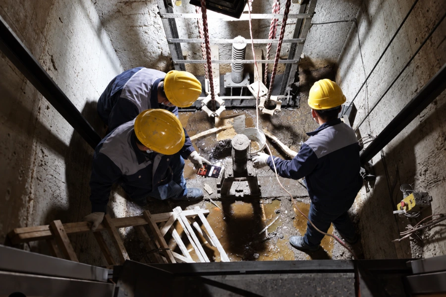
Step 1 — Measure the Available Clear Overhead
Measure from the highest landing’s finished floor level to the controlling permanent obstruction, not automatically to the roof slab.
Identify beams, slabs, structural supports and other components extending into the hoistway. A 4,500 mm floor-to-slab dimension provides only 4,200 mm of clear overhead where a beam projects 300 mm below the slab.
Step 2 — Confirm the Car Configuration
Check the finished car height and the equipment above it.
Architectural finishes, lighting, door equipment or customized car features can alter the vertical envelope even when the rated capacity does not change.
Step 3 — Review the Rated Speed
Confirm the selected speed against travel height, passenger demand and operating conditions.
If a lower-speed configuration is being considered to address restricted overhead, evaluate the effect on traffic handling as well as the dimensional benefit. Speed reduction should solve the building constraint without creating an unacceptable transportation-performance trade-off.
Step 4 — Compare Compatible Elevator Configurations
Compare applicable hydraulic, traction, MRL or other arrangements against the same project requirements.
A suitable alternative must fit the shaft while maintaining required capacity, traffic performance, installation conditions and safety provisions. A low-overhead option should therefore be evaluated as a complete system rather than as a dimensional feature.
Step 5 — Coordinate the Structural Layout
Identify whether the controlling obstruction is permanent or temporary and whether it can be relocated or modified.
Roof framing, structural beams, hoist beams and equipment supports should be coordinated with the responsible building design team before structural changes are assumed feasible.
Step 6 — Verify the Applicable Safety Requirements
Confirm the adopted elevator code, edition and relevant local requirements.
Existing buildings may be subject to different provisions from new construction in some jurisdictions. Physical fit alone does not establish that a compact or reduced-overhead configuration is acceptable.
Step 7 — Confirm the Project Layout
Coordinate the selected elevator with the architectural and structural drawings.
Before building interfaces are released for construction, the project documentation should identify the required overhead, pit depth, shaft dimensions, equipment arrangement and relevant structural interfaces.
When Should Elevator Overhead Be Confirmed?
Overhead should be coordinated before the shaft-head structure is frozen because later changes to car height, speed, machinery arrangement or structural beams can reopen the required dimension.
A practical coordination sequence is:
Concept design → preliminary elevator configuration → shaft and overhead allowance → elevator selection → project layout confirmation → structural coordination → construction
During concept design, preliminary capacity, speed and system assumptions can establish a planning allowance. Once the elevator is selected, those assumptions should be replaced by project-specific dimensions before roof beams, shaft-head slabs and other difficult-to-modify structural elements are finalized.
Preliminary Planning vs. Final Construction Dimensions
Planning guides help reserve building space before the elevator configuration is finalized. Construction dimensions require confirmed equipment and building interfaces.
| Preliminary Planning | Final Construction |
|---|---|
| Generic manufacturer dimensions | Approved project-specific dimensions |
| Assumed car height | Confirmed car and frame geometry |
| Preliminary speed | Final rated speed |
| Standard drive arrangement | Selected mechanical configuration |
| Estimated overhead allowance | Verified clear overhead |
| Early architectural coordination | Confirmed structural and installation interfaces |
The distinction is especially important for customized projects because changes to car dimensions, entrances or equipment layouts can invalidate dimensions taken from a standard catalog configuration.
Elevator Overhead Planning Checklist
Before finalizing the shaft head, verify:
| Item | Information to Confirm |
|---|---|
| Building datum | Highest landing finished floor elevation |
| Available space | Clear distance to lowest permanent obstruction |
| Elevator type | Hydraulic, traction, MRL or other selected system |
| Rated capacity | Required passenger or freight load |
| Rated speed | Confirmed operating speed |
| Car configuration | Interior height, frame and equipment arrangement |
| Terminal conditions | Applicable run-by and terminal movement requirements |
| Safety space | Applicable car-top clearance or protected-space provisions |
| Structural coordination | Roof beams, hoist beams and equipment supports |
| Regulatory framework | Applicable elevator code and adopted edition |
| Final documentation | Project-specific elevator layout |
For international projects, confirm that elevator documentation and construction drawings use consistent measurement datums and units.
Finalizing Elevator Overhead for Your Project
Elevator overhead is a building-interface dimension determined by the interaction of car geometry, rated speed, terminal movement, machinery arrangement, safety clearances and structural obstructions.
For project-specific applications, EKCNE evaluates overhead together with shaft dimensions, rated capacity, travel height, drive configuration and installation conditions. This allows the elevator configuration and building interfaces to be coordinated before final structural dimensions are released for construction.