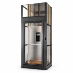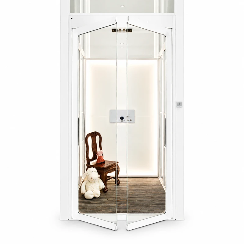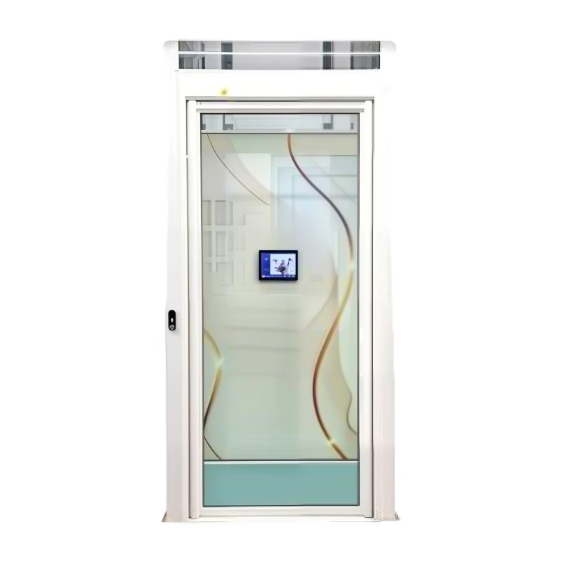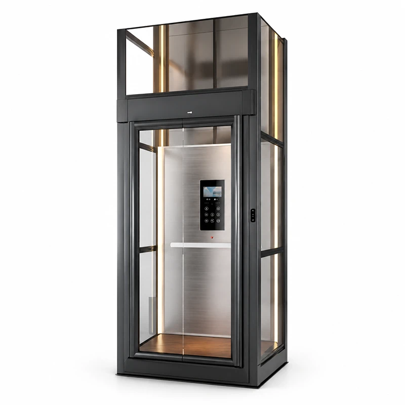
There is no universal elevator pit depth. For early planning, many conventional passenger elevator manufacturer configurations use pit dimensions within a broad range of roughly 1,200 to 2,000 mm, while higher-speed or specialized systems may require more.
This range is not an industry standard or code requirement. Final depth depends on rated speed, buffer arrangement, car and counterweight geometry, required safety spaces, pit equipment, elevator category and the applicable code. The project-specific elevator layout determines the final civil dimension.
Elevator Pit Depth at a Glance
The ranges below combine manufacturer planning dimensions and project examples. They support concept design but do not represent universal code minimums.
| Elevator Configuration | Illustrative Planning Range | Main Variables |
|---|---|---|
| Conventional passenger elevator around 1.0 m/s | About 1,200–1,500 mm | Buffer and car arrangement |
| Passenger elevator around 1.5–1.75 m/s | About 1,500–1,900 mm | Speed, buffer and under-car geometry |
| Example higher-speed configuration above 2.5 m/s | Around 2,000 mm or more | Buffer stroke and safety clearances |
| Reduced-pit passenger elevator | Project-specific | Protective measures and applicable code |
| Home or platform lift | Often substantially shallower | Product category, speed and governing standard |
Two elevators with the same rated capacity can require different pits if their speed, buffers, suspension arrangement or under-car equipment differ. Architectural pit dimensions should therefore remain provisional until the elevator configuration has been coordinated with the supplier.
What Is an Elevator Pit?
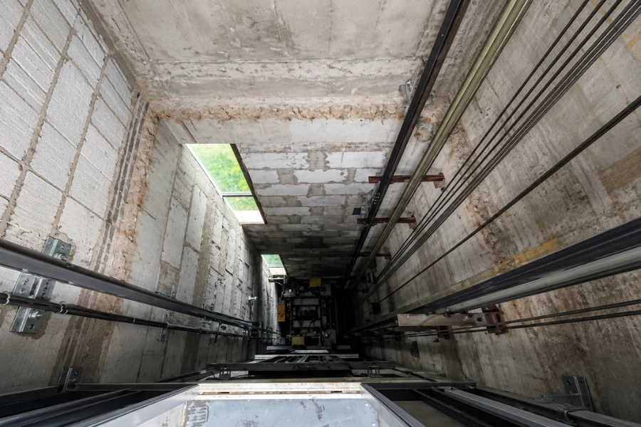
The elevator pit is the portion of the hoistway below the finished floor of the lowest landing. It provides the vertical space needed for safety clearances and components such as car and counterweight buffers, guide rail equipment, compensation equipment and inspection or access devices.
Its dimensions must therefore be coordinated with both the elevator layout and building conditions such as foundations, waterproofing, access and the space below the hoistway.
What Determines Elevator Pit Depth?
Pit depth results from the combined vertical space required by elevator equipment and mandatory safety clearances. The controlling requirement depends on the specific system configuration.
Rated Speed and Buffer Requirements
Rated speed affects the energy the buffer system must manage during specified overtravel conditions. As speed increases, buffer performance and travel requirements can increase, changing the vertical space needed for the buffer assembly and surrounding components.
Changing rated speed after pit design can therefore invalidate an earlier civil dimension.
Buffer Type and Arrangement
Pit depth must accommodate more than nominal buffer stroke. Buffer body height, supports, compressed position and the geometry of the car or counterweight around the buffer all contribute to the required space.
For this reason, a buffer stroke value alone cannot be converted directly into a civil pit depth.
Rated Load and Car Configuration
Rated load affects pit depth indirectly through car dimensions, frame design, buffer selection and component loads. A heavier elevator does not automatically require a proportionally deeper pit.
Rated speed generally has a more direct relationship with buffer travel, while rated load changes the component and system geometry that must fit within the pit. A 1,000 kg rating alone therefore does not determine pit depth.
Safety Clearance and Refuge Space
The pit must retain defined safety spaces under specified elevator conditions so technicians can work below the car.
These requirements can control pit geometry even when the buffers could physically fit into a shallower space. A code-defined safety condition therefore cannot be translated directly into one universal manufacturer pit dimension.
Equipment Inside the Pit
Depending on the elevator configuration, the pit can contain:
- Car buffers
- Counterweight buffers
- Compensation rope or chain equipment
- Guide rail components
- Governor rope tension equipment
- Pit stop devices
- Inspection controls
- Access ladders
- Electrical outlets and lighting
- Drainage or water-removal provisions where applicable
These components must fit while preserving the required equipment and under-car clearances.
Elevator Pit Depth Requirements by Standard
Elevator codes generally define safety conditions that the pit must satisfy rather than one depth for every elevator. The applicable code edition and elevator category must therefore be identified before a project-specific pit dimension can be established.
EN 81-20 and EN 81-50
For elevators within the scope of EN 81-20, pit design incorporates refuge spaces, vertical clearances, buffers and other equipment requirements.
EN 81-20 defines three types of refuge space for the pit.
| Position | Horizontal Space | Height |
|---|---|---|
| Standing | 0.40 × 0.50 m | 2.00 m |
| Crouching | 0.50 × 0.70 m | 1.00 m |
| Lying, pit only | 0.70 × 1.00 m | 0.50 m |
When the car is at the specified lowest position, EN 81-20 generally requires at least 0.50 m of free vertical distance between the pit floor and the lowest parts of the car. Defined reductions apply to specific components, including the apron, parts of vertically sliding car doors and certain car-frame parts, safety gears and guide shoes near the guide rails.
The final pit must satisfy these clearance and refuge-space conditions together with buffer travel, fixed pit equipment and guide rail requirements. EN 81-20 therefore does not translate into one nominal pit depth for every compliant elevator.
GB 7588 and GB/T 7588.1
Chinese elevator projects likewise coordinate pit dimensions with buffers, safety spaces, equipment and the selected elevator configuration.
The following values represent one example passenger elevator configuration with a rated load of up to 1,000 kg and a car clear height of approximately 2,400 mm. They are planning references rather than mandatory speed-to-depth values.
Example Passenger Elevator Configuration
| Rated Speed | Example Planning Pit Depth |
|---|---|
| 1.0 m/s | 1,450 mm |
| 1.75 m/s | 1,600 mm |
| 2.0 m/s | 1,700 mm |
| 2.5 m/s | 2,050 mm |
These figures are configuration examples, not universal minimum dimensions prescribed by GB 7588. Different buffers, car frames, suspension systems, capacities and project specifications can change the required pit, so the supplier’s project layout remains the basis for final civil coordination.
ASME A17.1/CSA B44
Under the North American code framework, pit depth must accommodate buffers, compensating sheaves where used, other pit equipment and the required bottom clearance and runby.
This framework does not establish one universal “minimum U.S. elevator pit” dimension. The code edition adopted by the local Authority Having Jurisdiction also needs to be confirmed because applicable requirements can vary by location and adoption cycle.
Why Elevator Pit Depth Increases With Speed
The relationship between speed and pit depth is primarily driven by how the elevator manages energy during abnormal terminal travel.
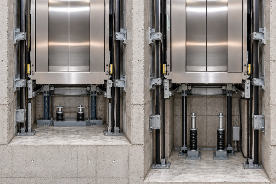
As rated speed increases, buffer performance and travel requirements can increase. The resulting buffer stroke, physical assembly and required clearances can demand more vertical space.
The engineering relationship is approximately:
Rated speed → buffer requirement → buffer stroke and assembly → required clearances → pit geometry
Speed still does not determine pit depth by itself. Two elevators at the same rated speed can require different pits because their buffer technology, car frames and equipment layouts differ.
A pit reserved for a 1.0 m/s elevator should therefore be rechecked if traffic analysis later changes the specification to 2.0 or 2.5 m/s.
Why a 150 mm Pit and a 1,500 mm Pit Can Both Be Correct
A 100 or 150 mm pit in one product specification and a 1,500 mm pit in another do not necessarily conflict. The figures may refer to different elevator categories, operating conditions and regulatory frameworks.
Conventional Passenger Elevators
A conventional passenger elevator must provide the buffers, safety spaces and operating components required by its system configuration and governing code. Its pit is therefore derived from the complete safety and equipment arrangement.
Reduced-Pit Passenger Elevators
Existing buildings may not provide the pit normally required by a conventional configuration. Where the applicable regulatory framework permits, reduced-pit systems can use additional protective measures to provide safe working conditions when personnel enter the pit.
This exchanges part of the civil-space requirement for additional elevator-system measures. It should not be interpreted as a general basis for reducing pits in new construction.
Home Elevators and Platform Lifts
Some home elevators and vertical lifting platforms use pits ranging from tens to several hundred millimeters, and some configurations can be installed on a finished floor.
Their speed, travel, equipment architecture and governing requirements can differ from conventional passenger elevators. A 150 mm home-lift pit is therefore not a smaller version of a 1,500 mm commercial passenger-elevator pit.
What If the Available Pit Is Too Shallow?
A shallow existing pit should first be treated as a design constraint rather than an excavation instruction. The available options depend on the elevator category, applicable code, required capacity and speed, buffer arrangement, surrounding structure and space below the pit.
Existing Buildings
Excavation can be restricted by:
- Foundation geometry
- Structural slabs
- Underground utilities
- Existing basements
- Groundwater
- Adjacent foundations
- Usable rooms below the proposed elevator
For projects governed by European standards, EN 81-21 provides a framework for certain new passenger and goods-passenger elevators installed in existing buildings where normal pit or headroom conditions cannot be achieved.
Reduced-pit solutions can require additional protective systems and mechanical measures. They may avoid or limit structural excavation while adding equipment, commissioning requirements and maintenance considerations.
New Construction
Before pit construction, the project should have sufficiently defined the elevator category, rated capacity, car size, rated speed, shaft dimensions, pit requirement and overhead requirement.
Changing these parameters after structural work can require excavation, slab modification or a different elevator configuration. Pit and overhead dimensions should therefore be coordinated with the preliminary elevator layout before the civil design is frozen.
Why the Space Below the Elevator Pit Matters
Conditions beneath the pit can determine whether a proposed depth is structurally and operationally practical.
Soil and Foundations
A ground-level pit must be coordinated with foundations and surrounding structural elements. Additional depth can interfere with footings, change local foundation details or place the pit in more demanding groundwater conditions.
Accessible or Occupied Space Below the Pit
A pit above a basement, parking level, corridor, store or other accessible area creates different structural and elevator-safety conditions from a pit bearing directly against the ground.
This condition should be identified before the rail, counterweight and safety arrangements are finalized because applicable requirements for spaces beneath the hoistway can affect the system design.
Groundwater
A deeper pit can extend below the local groundwater level or into zones with greater moisture exposure.
This affects waterproofing, construction joints, water-removal strategy, corrosion exposure and maintenance conditions. Increasing pit depth can therefore create additional civil and lifecycle requirements even when additional excavation is structurally possible.
Elevator Pit Waterproofing and Drainage
Persistent water in the pit can corrode buffers, guide components and other equipment and create unsuitable inspection conditions.
Waterproofing should address groundwater and construction-water intrusion at the structural interface. Where drainage or pumping is required, it should be coordinated with the applicable building and elevator requirements rather than using the elevator pit as the building’s general drainage sump.
Common Elevator Pit Planning Mistakes
| Planning Mistake | Possible Project Consequence |
|---|---|
| Using a brochure pit depth without checking the configuration | Civil work may not match the ordered elevator |
| Selecting elevator speed after pit construction | Buffer and clearance requirements may no longer fit |
| Treating code requirements as one fixed pit dimension | Incorrect structural planning |
| Assuming higher capacity always means a proportionally deeper pit | Incorrect equipment assumptions |
| Mixing home-lift and passenger-elevator dimensions | Unrealistic shallow-pit expectations |
| Ignoring accessible space beneath the pit | Late safety or structural redesign |
| Treating the pit as general drainage space | Water intrusion and equipment deterioration |
| Relying only on old architectural drawings | Existing structure may differ from the design record |
These errors are easier to correct before structural work because pit changes made later can affect excavation, slabs, foundations and the selected elevator configuration.
How to Determine Elevator Pit Depth Before Construction
A project-specific pit depth can be developed through the following sequence.
1. Identify the Applicable Code
Confirm the elevator safety standard, adopted edition and local requirements at the installation location. These establish the safety conditions the pit must satisfy.
2. Define the Elevator Category and Building Use
Determine whether the project requires a passenger, hospital, freight, home or other elevator type. Building use also establishes traffic and operational requirements that influence system selection.
3. Set Rated Load and Car Size
Define capacity from passenger demand, building function or freight-handling requirements. This establishes the basic car and frame geometry.
4. Set Rated Speed
Select speed based on travel height, traffic requirements and expected service. Speed can change buffer requirements and therefore the required pit arrangement.
5. Select the Elevator Configuration
Define the drive, suspension arrangement, car frame, counterweight and buffer configuration sufficiently to establish the physical lower-hoistway layout.
6. Verify Safety Spaces and Pit Equipment
Check the applicable buffer requirements, bottom clearances, refuge spaces, equipment clearances, pit access and inspection provisions. Required equipment must fit without occupying prescribed safety spaces.
7. Review Building Conditions
Verify foundation geometry, structural slabs, available excavation, groundwater, underground services, space below the pit and construction or maintenance access.
A technically suitable elevator configuration may need revision if these building conditions prevent the required pit from being constructed safely or economically.
8. Freeze the Dimension With the Project Layout
The elevator supplier should issue a project-specific layout showing the required pit, shaft and overhead dimensions before the corresponding civil dimensions are finalized.
The architectural pit dimension should remain provisional until the selected elevator configuration has been checked against the applicable code and manufacturer layout.
Information to Send an Elevator Supplier
To evaluate pit requirements, provide:
- Project location
- Building type
- New or existing construction
- Number of floors and stops
- Total travel height
- Required capacity
- Desired rated speed
- Available shaft width and depth
- Available pit depth
- Available overhead
- Machine-room availability
- Space or structure below the pit
- Groundwater or excavation constraints
- Local code or project specification where known
These inputs allow the engineering team to compare the building envelope with conventional, reduced-pit or customized configurations before civil dimensions are finalized.
EKCNE supports this project-specific coordination by evaluating building conditions, elevator performance requirements and manufacturing parameters as part of elevator configuration planning.
Project Planning Takeaway
Elevator pit depth is an engineering output of the elevator configuration, safety requirements and building conditions rather than an architectural dimension that should be selected independently.
Concept-stage dimensions can reserve space, but the final pit should be coordinated against rated speed, buffers, safety spaces, equipment, structural conditions and the applicable code before civil construction is finalized. Existing-building projects additionally require verification of the actual pit, shaft, overhead and surrounding structure before the elevator configuration is selected.