Elevator speed selection requires an assessment of travel height, passenger demand, stopping patterns, and the performance expected from the elevator group. Building height provides an initial reference, but it does not establish the appropriate rated speed by itself.
The selection process should compare running time, transportation capacity, equipment compatibility, and installation constraints before a final specification is issued.
What Is Elevator Rated Speed?
Elevator rated speed is the nominal operating speed assigned to an elevator, expressed in meters per second (m/s).
The car reaches this speed only when the available travel distance and motion profile permit it. During shorter journeys, acceleration and deceleration may occupy the entire movement cycle.
Elevator Speed Categories
Engineering references use different classifications. The following ranges represent one engineering classification rather than universally adopted regulatory definitions.
| Speed category | Rated speed | General application |
|---|---|---|
| Low-speed | ≤ 1.0 m/s | Short-rise and selected special-purpose applications |
| Medium-speed | > 1.0 to 2.5 m/s | Many residential and commercial applications |
| High-speed | > 2.5 to 6.0 m/s | High-rise passenger transportation |
| Ultra-high-speed | > 6.0 m/s | Selected very tall buildings and specialized systems |
These ranges are descriptive. They should not be interpreted as recommended speeds for specific building heights or floor counts.
How to Choose Elevator Speed for Your Building
A preliminary elevator speed assessment can be organized into five steps.
Step 1 — Calculate Travel Height
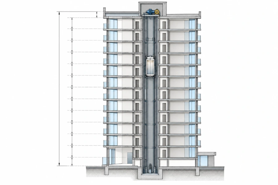
Travel height is the vertical distance between the lowest and highest served landings.
For a building with uniform floor-to-floor heights:
\[ H=(F-1)h \]
Where:
- \(H\) is travel height in meters.
- \(F\) is the number of served floors.
- \(h\) is the floor-to-floor height in meters.
For example, a 15-floor building with 3.5-meter floor intervals has an approximate travel height of:
\[ H=(15-1)\times3.5=49\text{ m} \]
This calculation assumes 14 equal floor intervals. Where floor elevations vary, use the actual vertical distance from the architectural drawings.
Travel height helps establish the available distance for acceleration, constant-speed movement, and deceleration.
Step 2 — Define Transportation Requirements
Identify the building population, floor distribution, peak passenger arrivals, and expected destinations.
Different service problems require different performance indicators.
| Transportation requirement | Indicator to evaluate |
|---|---|
| Long journeys between distant floors | In-car travel time |
| Long gaps between successive elevator departures | Group interval |
| Passenger queues during peak demand | Handling capacity and passenger waiting time |
| Congestion at specific landings | Destination distribution and dispatching |
| Heavy service or equipment movement | Car capacity, dimensions, and loading cycle |
These indicators should be established before comparing rated speeds.
Step 3 — Determine Stopping Patterns
Identify whether the elevator serves every floor, operates within a zone, or travels express between selected landings.
Each intermediate stop introduces deceleration, leveling, door operation, passenger transfer, and acceleration.
Expected stopping frequency therefore affects the proportion of the operating cycle that can benefit from higher rated speed.
Step 4 — Compare System Configurations
Evaluate feasible combinations of rated speed, car capacity, elevator quantity, and control strategy.
Speed primarily influences running time. Capacity affects the number of passengers transported per trip, while elevator quantity influences service frequency and group throughput.
These variables interact, so each proposed configuration should be evaluated using its own traffic assumptions.
Step 5 — Confirm Equipment and Building Compatibility
Check the proposed rated load, travel height, drive arrangement, shaft dimensions, pit depth, overhead clearance, and maintenance access.
For modernization projects, identify which existing components will remain in service and whether they are suitable for the proposed operating conditions.
Elevator Speed by Building Type and Height
Building use influences traffic distribution, stopping patterns, and service priorities.
| Building type | Main operating condition | Speed selection consideration |
|---|---|---|
| Low-rise residential | Short journeys | Limited constant-speed travel |
| High-rise residential | Longer journeys and residential peak demand | Travel time, capacity, and car quantity |
| Office buildings | Concentrated arrival and departure traffic | RTT, interval, handling capacity, and zoning |
| Hotels | Guest, luggage, event, and service traffic | Passenger and service traffic arrangements |
| Hospitals | Bed, equipment, staff, and visitor movement | Car dimensions, leveling, ride comfort, and availability |
| Freight and industrial buildings | Heavy loads and loading-intensive cycles | Rated load and complete operating-cycle time |
| Very tall buildings | Long express journeys and multiple zones | High-speed operation and service zoning |
Residential and Office Buildings
For residential buildings, the relevant inputs include occupants per floor, total population, travel height, and expected peak passenger demand.
In taller residential projects, increasing speed can reduce long journeys, but the elevator group must also provide sufficient passenger handling capacity.
Office buildings often require a more detailed examination of morning up-peak traffic. The analysis should estimate passenger arrivals, car loading, expected stops, and group performance.
In taller office buildings, zoning can reduce the number of floors served by each group and introduce express travel sections. This changes both the expected RTT and the benefit available from higher rated speed.
Hotels and Hospitals
Hotels should establish how guest, luggage, housekeeping, and service traffic will be distributed among elevators.
Where these activities share the same cars, loading patterns and service stops must be included in the traffic assessment.
Hospital elevator selection requires suitable car and door dimensions for beds and medical equipment, along with reliable leveling and appropriate ride characteristics.
These operational requirements should be defined before speed is finalized.
Freight and Industrial Buildings
Freight elevator productivity depends on loading, vertical travel, unloading, and return time.
Where loading and unloading dominate the cycle, reducing running time may have a limited effect on completed trips.
Rated load, cargo dimensions, door arrangement, loading method, and positioning requirements should therefore be evaluated alongside speed.
How Speed Affects Travel Time and Traffic Performance
Elevator traffic analysis relates individual car operation to the transportation performance of the group.
Round trip time, interval, and handling capacity are useful measures for conventional group comparisons.
Round Trip Time
Round trip time (RTT) is the estimated duration of a complete elevator service cycle under specified traffic assumptions.
In a conventional up-peak model, this includes loading passengers at the main terminal, serving their destination floors, and returning for the next trip.
RTT contains several time components.
| Component | Main influencing factors |
|---|---|
| Running time | Travel distance, rated speed, acceleration, and deceleration |
| Stopping time | Number of stops, leveling, and motion transitions |
| Door operation | Opening and closing times |
| Passenger transfer | Passenger quantity, door width, and boarding behavior |
Increasing rated speed primarily reduces the running-time component when sufficient travel distance is available.
Interval and Handling Capacity
For a simplified conventional elevator group, the average interval is:
\[ I=\frac{RTT}{N} \]
Where \(I\) is the calculated average interval in seconds, \(RTT\) is round trip time in seconds, and \(N\) is the number of elevators.
The corresponding five-minute handling capacity is:
\[ HC_5=\frac{300PN}{RTT} \]
Where \(P\) is the assumed average number of passengers transported per car trip.
These relationships assume a conventional group operating under comparable, steady up-peak conditions. The calculated interval represents the average time between successive car departures or arrivals at the main terminal, not actual passenger waiting time.
Handling capacity is expressed as passengers per five minutes. To express it as a percentage of the building’s service population, divide the passenger count by that population and multiply by 100.
Neither formula directly predicts passenger waiting time or total time to destination.
Example — Comparing Speed, Capacity, and Elevator Quantity
Consider a hypothetical office elevator group with three cars, 10 passengers per trip, and an RTT of 150 seconds.
The baseline interval is:
\[ I=\frac{150}{3}=50\text{ seconds} \]
The baseline five-minute handling capacity is:
\[ HC_5=\frac{300\times10\times3}{150}=60 \]
Three hypothetical changes produce the following results.
| Configuration | RTT | Passengers per trip | Cars | Interval | Five-minute capacity |
|---|---|---|---|---|---|
| Baseline | 150 s | 10 | 3 | 50.0 s | 60 |
| Higher speed | 135 s | 10 | 3 | 45.0 s | 66.7 |
| Greater capacity | 160 s | 12 | 3 | 53.3 s | 67.5 |
| Additional elevator | 150 s | 10 | 4 | 37.5 s | 80 |
The values are illustrative calculations based on assumed RTT, passenger loading, and elevator quantities. They are not measured results or performance predictions for a particular building.
The RTT values are independent teaching assumptions. They have not been derived from specific rated speeds, equipment specifications, or traffic simulations.
Higher speed improves the calculated interval and handling capacity when the reduction in running time lowers RTT without changing passenger loading or car quantity.
Greater capacity can increase throughput, although additional passengers may increase boarding time and the expected number of stops. The example assumes a longer RTT to illustrate this interaction.
An additional elevator reduces the calculated interval and increases handling capacity when RTT per car remains unchanged. Its feasibility depends on available shaft space, equipment costs, and building design.
The appropriate alternative depends on whether the project needs shorter in-car journeys, greater passenger throughput, or more frequent service.
For an actual project, RTT and passenger loading should be recalculated for each proposed configuration. Traffic simulation may be necessary where passenger distribution, dispatching, mixed traffic, or building complexity makes simplified calculations insufficient.
Traffic Analysis References
Professional references for elevator traffic planning include:
- CIBSE Guide D 2025 — Transportation Systems in Buildings
- Elevator World — Fundamentals of Traffic Analysis
- ISO 8100-32:2020, which addresses passenger elevator traffic planning and selection within its defined scope.
These references provide a basis for structured traffic analysis. They do not validate the hypothetical values used in the example.
Acceleration, Deceleration, and Short-Trip Performance
The time saved by increasing rated speed depends on whether the elevator can reach that speed during the available journey.
A Simplified Acceleration Distance Model
Assume the elevator starts from rest, accelerates at a constant rate, and decelerates at the same magnitude until it stops.
Ignoring jerk-limited transitions, the combined acceleration and deceleration distance is:
\[ d=\frac{v^2}{a} \]
Where \(d\) is distance in meters, \(v\) is target speed in m/s, and \(a\) is the assumed acceleration and deceleration magnitude in m/s².
At an assumed acceleration of 1.0 m/s²:
| Rated speed | Combined acceleration and deceleration distance |
|---|---|
| 1.0 m/s | 1.00 m |
| 1.6 m/s | 2.56 m |
| 2.5 m/s | 6.25 m |
| 3.0 m/s | 9.00 m |
Under these assumptions, the distance increases with the square of speed. Doubling the target speed requires four times the combined acceleration and deceleration distance.
This is an idealized motion model, not a manufacturer-specific acceleration curve.
Example — A 3.5-Meter Journey
Consider two elevators traveling between floors separated by 3.5 meters, both using an assumed acceleration and deceleration magnitude of 1.0 m/s².
| Parameter | Elevator A | Elevator B |
|---|---|---|
| Rated speed | 1.6 m/s | 2.5 m/s |
| Distance needed to reach rated speed and stop | 2.56 m | 6.25 m |
| Reaches rated speed over 3.5 m | Yes | No |
| Calculated movement time | 3.79 s | 3.74 s |
Elevator A reaches 1.6 m/s and completes a short constant-speed phase.
Elevator B cannot reach 2.5 m/s. Under the simplified model, its peak speed is approximately 1.87 m/s.
The calculated movement-time difference is approximately 0.05 seconds.
This example excludes jerk control, leveling, controller transitions, and equipment-specific limits. It illustrates the relationship between rated speed and travel distance rather than predicting actual elevator performance.
Ride Comfort and Leveling
Jerk is the rate of change of acceleration. It affects how smoothly passengers experience the transition between acceleration, constant-speed travel, and deceleration.
Elevator controllers and variable-voltage variable-frequency (VVVF) drives manage the motion profile through motor control and position feedback.
Leveling performance also depends on control accuracy, braking behavior, and mechanical condition.
For hospitals and applications involving mobility equipment, the selection should evaluate ride comfort and leveling performance alongside journey time.
How Drive Systems Affect Speed Selection
Drive technology affects the feasible rated speed, load capacity, travel height, equipment layout, and maintenance requirements.
Hydraulic vs. Traction Elevators
| Selection factor | Hydraulic elevators | Traction elevators |
|---|---|---|
| Typical application | Selected low-rise and heavy-load projects | Low-rise through high-rise projects |
| Speed suitability | Generally lower-speed applications | Broad range, including high-speed systems |
| Travel height | Commonly more limited | Suitable for longer lifting heights |
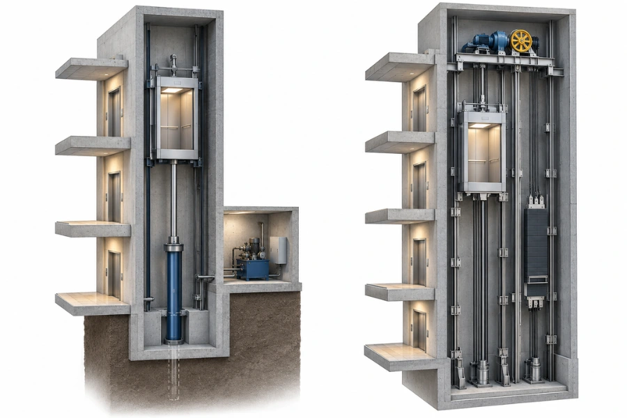
| Main equipment | Hydraulic cylinder and power unit | Traction machine, suspension, and counterweight |
| Installation considerations | Hydraulic equipment space, fluid system, and operating cycle | Machine arrangement, suspension, shaft geometry, and drive control |
Traction systems are generally more suitable for high-speed operation and long travel distances.
Hydraulic systems may be suitable when their load-handling characteristics and installation requirements match the project.
The applicable standard must also be checked. For example, EN 81-20:2020 does not cover hydraulic lifts with a rated speed exceeding 1 m/s. This scope limitation does not establish a universal prohibition under other regulatory frameworks.
Geared vs. Gearless Traction Machines
Geared traction machines use a gearbox between the motor and traction sheave, while gearless machines drive the sheave directly.
Gearless machines are available across a broad range of rated speeds and are not limited to high-rise applications.
Machine selection should consider rated load, speed, suspension arrangement, torque requirements, equipment dimensions, and maintenance access.
MRL vs. Machine Room Configurations
Machine-room-less (MRL) describes equipment placement, not a drive principle or speed category.
MRL arrangements position the machine and associated equipment within the shaft arrangement instead of a conventional separate machine room.
Feasibility depends on rated load, travel height, equipment dimensions, shaft space, maintenance access, and applicable installation requirements.
Where these conditions cannot be satisfied, a machine-room arrangement may be more appropriate.
Safety and Shaft Requirements at Different Speeds
Changing rated speed can affect the suitability of safety equipment, mechanical components, and installation clearances.
The technical assessment should identify the components affected by the proposed operating conditions.
Overspeed Protection, Safety Gear, and Braking
Overspeed protection, safety gear, and braking systems must be compatible with the elevator’s rated speed, rated load, and mechanical configuration.
A speed increase may require reassessment of governor operating characteristics, safety gear suitability, braking performance, and associated drive components.
Compatibility must be established using the applicable requirements and approved equipment documentation.
Buffers and Pit Requirements
Buffer type, stroke, mounting arrangement, and required clearances can influence pit depth.
Increasing rated speed may change the buffer configuration or installation requirements, but it does not automatically require a deeper pit in every project.
The required arrangement depends on the equipment design, applicable safety provisions, and available installation space.
Guide Systems and Shaft Compatibility
Guide rails, guide shoes, suspension components, and machine arrangements must be suitable for the intended operating conditions.
Higher-speed applications may require more demanding control of guide rail alignment, vibration, and ride quality.
An engineering assessment should consider rail and bracket suitability, guide equipment, suspension arrangements, shaft clearances, and available pit and overhead dimensions.
Speed Changes During Modernization
Increasing an existing elevator’s rated speed requires evaluation of the complete installation rather than the controller alone.
The assessment should identify retained and replacement components, including the machine, suspension, brakes, safety devices, guide equipment, buffers, and control system.
The proposed modification must also satisfy applicable testing, inspection, and approval requirements.
If higher speed requires extensive equipment replacement or shaft modification, the investment should be compared with the calculated transportation benefit.
Applicable Standards and Market Requirements
Elevator safety requirements depend on the project location, equipment type, applicable code, adopted edition, and whether the work involves a new installation or modernization.
| Market | Relevant framework | Required verification |
|---|---|---|
| European Union | Directive 2014/33/EU and applicable EN 81 standards | Confirm the applicable requirements, harmonized standards, and conformity assessment route |
| United States | ASME A17.1/CSA B44 and locally adopted regulations | Confirm the edition adopted by the authority having jurisdiction |
| Canada | ASME A17.1/CSA B44 and provincial requirements | Confirm the adopted edition and applicable provincial provisions |
| Other markets | Applicable national regulations and adopted standards | Verify local requirements before equipment selection |
EN 81-20:2020 and EN 81-50:2020 are relevant references for many passenger and goods-passenger lift installations within their respective scopes.
However, publication of a newer standard does not automatically establish its legal adoption or harmonized status in a particular market.
Specific requirements for overspeed protection, safety gear, braking, buffers, and installation clearances must be checked against the applicable adopted standards and approved manufacturer documentation.
The engineering guidance in this article does not establish regulatory compliance for a particular elevator model or project.
Lifecycle Cost and Speed Selection Tradeoffs
Elevator configurations should be compared against the same transportation requirements and operating assumptions.
| Cost category | Variables to compare |
|---|---|
| Initial investment | Drive equipment, controls, safety components, installation, and commissioning |
| Operating cost | Energy consumption under representative traffic conditions and standby demand |
| Maintenance | Equipment access, inspections, component wear, spare parts, and replacement requirements |
| Building impact | Shaft quantity, equipment space, and structural modifications |
A higher-speed configuration may require different machinery or safety equipment without delivering a proportional reduction in RTT.
An additional elevator can improve group service frequency but requires another shaft and equipment set.
A larger car can increase passenger throughput while changing equipment ratings, shaft dimensions, and passenger transfer time.
Energy Consumption and Rated Speed
Rated speed alone is insufficient to predict energy consumption.
Energy performance also depends on loading, counterweight balance, travel patterns, motor and drive efficiency, regenerative operation, and standby demand.
Energy comparisons should therefore use representative operating conditions rather than speed ratings alone.
Comparing Lifecycle Value
A useful project comparison combines traffic performance, equipment cost, installation feasibility, energy consumption, and maintenance requirements.
Where two configurations provide similar service performance, shaft space, maintenance accessibility, and replacement costs may determine the preferred option.
Elevator Speed Selection Checklist for Project Buyers
An elevator request for quotation should provide the inputs needed to evaluate equipment suitability and transportation performance.
| Project input | Information to provide |
|---|---|
| Building use | Residential, office, hotel, hospital, industrial, or mixed-use |
| Floors served | Terminal landings and intermediate stops |
| Travel height | Actual vertical distance between terminal landings |
| Population | Expected occupants and floor distribution |
| Peak traffic | Arrival rates, destinations, and operating periods |
| Elevator group | Proposed car quantity and service zones |
| Rated load | Required capacity and expected passenger loading |
| Car and doors | Car dimensions, door width, and opening type |
| Shaft conditions | Width, depth, pit, overhead, and equipment access |
| Applicable standards | Project country and regulatory framework |
| Lifecycle requirements | Maintenance access, energy objectives, and service arrangements |
For projects with significant passenger traffic, the proposal should compare feasible speed, capacity, and car quantity combinations.
Each option should state its traffic assumptions, calculated or simulated performance, equipment configuration, and installation requirements.
Conclusion
Elevator speed should be selected by comparing the transportation performance of feasible system configurations rather than using building height alone.
The final decision should establish whether higher speed provides sufficient travel-time or traffic-performance benefit to justify its equipment, installation, safety, and lifecycle requirements.