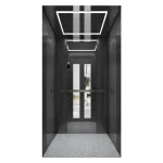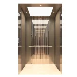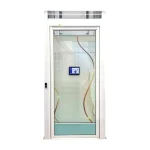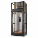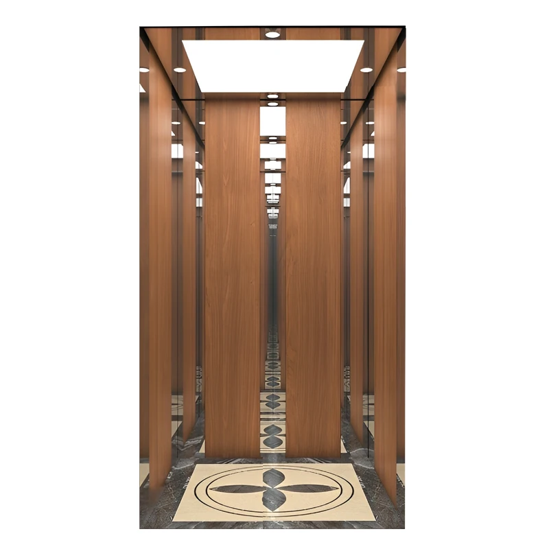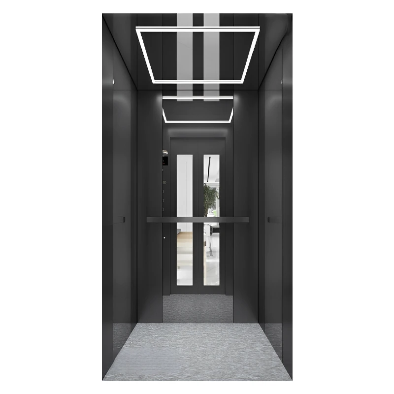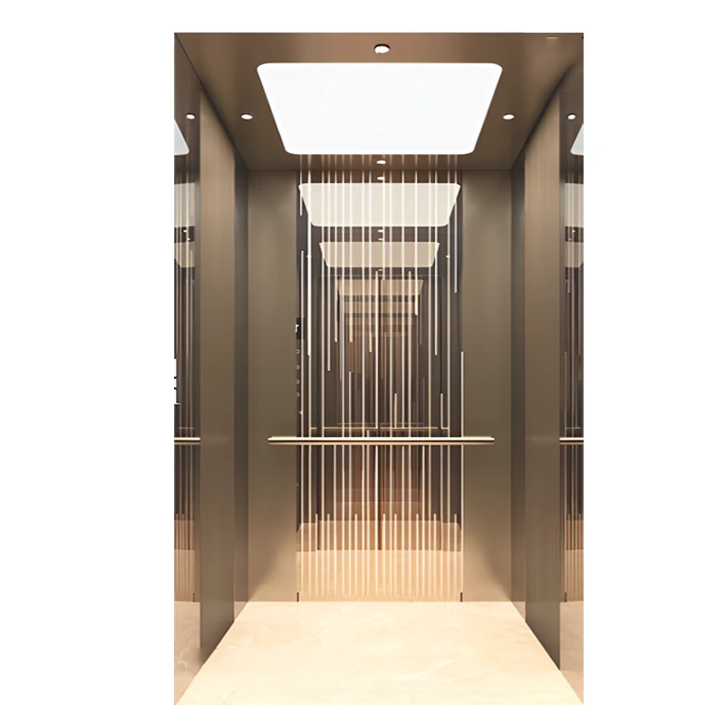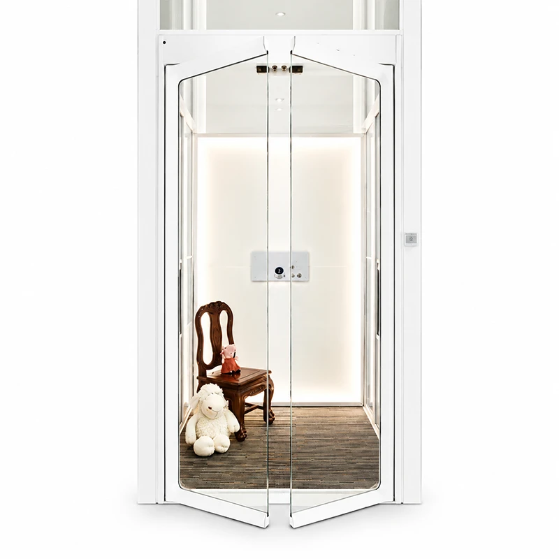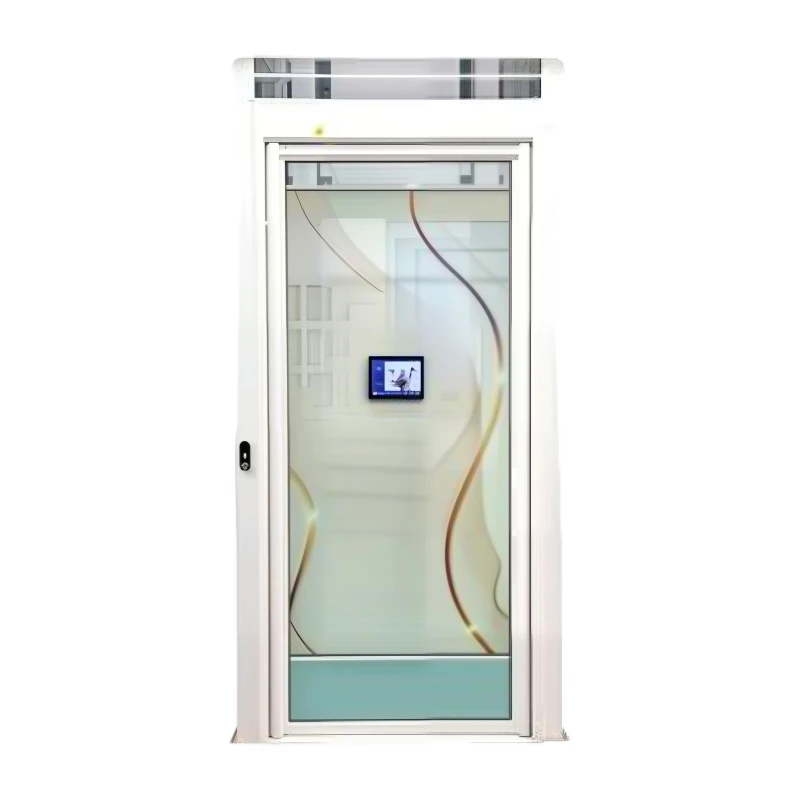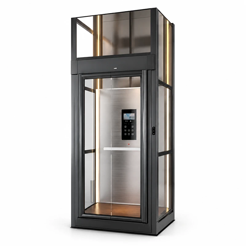
The minimum space required for an elevator depends on its type, rated capacity, shaft arrangement, and building structure. Compact home lifts may use a smaller equipment footprint than conventional enclosed elevators, while a residential elevator may require a clear hoistway of approximately 5 × 5 ft (1.52 × 1.52 m) as an initial planning reference.
Commercial passenger elevators generally require larger shafts. For example, an illustrative 1000 kg configuration uses a 1600 × 1400 mm car within a 2150 × 2000 mm clear hoistway. This is a dimensional example, not a universal minimum.
Floor area alone cannot establish installation feasibility. The selected system must also fit the available pit, overhead, structural openings, landing entrances, and equipment access arrangements.
How Much Space Does an Elevator Need?
The required area depends on whether the measurement describes the equipment footprint, clear shaft, or structural opening.
| Elevator Application | Preliminary Space Reference | Measurement Basis |
|---|---|---|
| Compact self-contained home lift | Product-specific compact footprint | Equipment dimensions, excluding additional access or construction space unless stated |
| Conventional residential elevator | Approximately 5 × 5 ft (25 sq ft) | Illustrative clear hoistway |
| Commercial passenger elevator | Depends on rated capacity and equipment arrangement | Manufacturer-defined clear hoistway |
These figures describe different measurement boundaries. A compact lift’s exterior dimensions should not be compared directly with the clear shaft dimensions of a conventional passenger elevator.
Four measurements determine whether a proposed location can accommodate the equipment:
- Car dimensions: Usable passenger or cargo compartment dimensions.
- Clear hoistway dimensions: Unobstructed space available inside the shaft.
- Structural opening dimensions: Building opening required for the shaft and associated construction.
- Vertical dimensions: Pit, travel distance, and upper-shaft space required by the selected system.
For new construction, the clear hoistway must be coordinated with shaft wall construction. For an existing building, the survey must also identify projections and dimensional variations along the travel path.
Minimum Elevator Shaft Dimensions by Capacity
Rated capacity influences car size, but it does not independently determine shaft dimensions. Door arrangement, counterweight location, car frame geometry, and guide system design also affect the required width and depth.
For example, the following 1000 kg passenger elevator configuration illustrates the relationship between the car and the clear hoistway.
| Parameter | Illustrative Dimension |
|---|---|
| Rated capacity | 1000 kg |
| Car width × depth | 1600 × 1400 mm |
| Clear shaft width × depth | 2150 × 2000 mm |
This example is retained from the supplied technical reference material for dimensional comparison. Its specific product model, entrance arrangement, and counterweight position have not been established. It is not a standardized minimum or a construction-ready layout.
For actual projects, shaft dimensions must be selected from the manufacturer’s drawings for the required capacity, entrance arrangement, travel, and equipment configuration.
Why Can Elevators With the Same Capacity Need Different Shaft Sizes?
A side-mounted counterweight occupies part of the shaft width, while a rear-mounted arrangement requires space behind the car. The resulting shaft proportions depend on the complete suspension and car frame layout.
Entrance configuration also matters. Center-opening and side-opening doors use different mechanisms, while a through-car arrangement introduces an entrance at the opposite end of the car.
Consequently, two 1000 kg elevators may provide similar usable car areas but require different shaft width-to-depth ratios. Door and counterweight arrangements should be confirmed before structural openings are finalized.
What Affects Elevator Shaft Size?
The clear hoistway must accommodate the car assembly and surrounding mechanical equipment rather than the passenger compartment alone.
Car Dimensions vs. Hoistway Dimensions
Using the illustrative 1000 kg configuration:
| Measurement | Dimensions | Horizontal Area |
|---|---|---|
| Car interior | 1600 × 1400 mm | 2.24 m² |
| Clear hoistway | 2150 × 2000 mm | 4.30 m² |
| Difference | — | 2.06 m² |
The car interior represents approximately 52% of the clear hoistway’s horizontal area in this example.
The remaining area accommodates the external car structure, guide systems, counterweight arrangement, door equipment, and required separations. It is not a uniform clearance around the car, and the calculation excludes shaft wall thickness.
A building opening that accommodates the car dimensions alone may therefore be insufficient for the complete elevator.
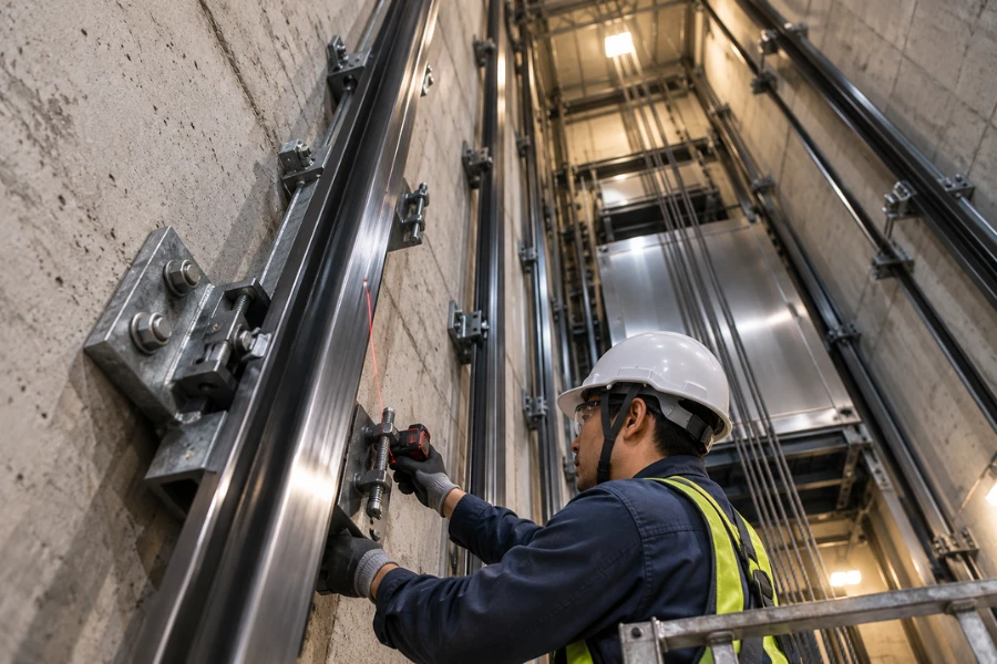
Guide Rail Supports and Installation Tolerances
Guide rail brackets require suitable fixing positions on the supporting structure. Their geometry and adjustment range influence the space available for rail alignment.
Beams, wall projections, and construction deviations can interfere with bracket installation or moving equipment, even when nominal shaft dimensions appear sufficient.
The manufacturer’s permitted shaft tolerances and equipment envelope must be checked against actual building measurements.
How Much Pit Depth and Overhead Clearance Is Required?
An elevator shaft must provide sufficient space below the lowest landing and above the highest landing for the selected equipment and applicable safety provisions.
Pit and overhead requirements depend on the elevator configuration, not simply its horizontal footprint.
Elevator Pit Depth Requirements
The pit provides space below the lowest landing for components such as buffers and lower guide-system equipment, together with required clearances under specified conditions.
Pit depth is influenced by buffer arrangement and stroke, car understructure, suspension design, and rated speed. Speed can affect equipment selection, but it does not independently determine the required pit depth.
Top-Floor Height vs. Hoistway Overhead
Manufacturers may use different labels and reference points for upper-shaft dimensions. The measurement endpoints shown on the general arrangement drawing determine how each value should be interpreted.
| Term | Meaning | Design Implication |
|---|---|---|
| Top-floor height | Distance from the highest finished landing to a specified upper structural reference | Check the manufacturer’s measurement endpoints |
| Hoistway overhead | Available vertical space in the upper shaft under the applicable drawing convention | Must accommodate upper equipment and required space |
| Clearance above the car | Separation required under specified car and equipment positions | Depends on the design and applicable safety provisions |
Finished ceiling height does not necessarily represent usable elevator overhead. Roof beams or slab projections may reduce the available space.
Machine-room-less elevators also require upper-shaft coordination because machinery and associated components may be located within the hoistway.
Space Requirements by Elevator Type
Elevator systems differ in where they place drive equipment, how they support the car, and what access they require for maintenance.
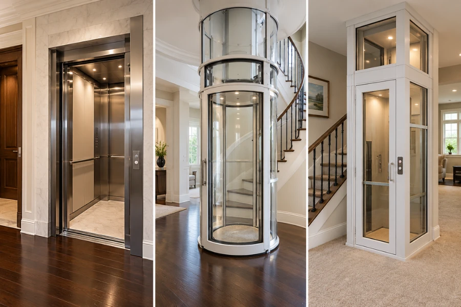
The smallest equipment footprint is not necessarily the configuration that uses the least practical building space.
| Elevator System | Potential Space Advantage | Main Constraint | Typical Application |
|---|---|---|---|
| Traction elevator | Multiple car and equipment layouts | Hoistway, suspension, guide systems, and associated equipment | Residential and commercial buildings |
| Machine-room-less traction elevator | No conventional separate machine room | Machinery location, shaft dimensions, and service access | Apartments, hotels, and offices |
| Hydraulic elevator | Flexible equipment arrangements for selected low-rise projects | Hydraulic equipment space and pit configuration | Low-rise passenger and selected freight applications |
| Pneumatic home elevator | Compact self-contained construction | Limited capacity, interior dimensions, and application range | Private residences |
| Through-floor home lift | May avoid a conventional enclosed shaft | Floor openings, travel limits, and access requirements | Selected residential retrofits |
Does a Machine-Room-Less Elevator Save Space?
An MRL elevator eliminates the conventional separate machine room by incorporating traction machinery into the elevator system layout.
This can reduce the building area allocated to elevator equipment. However, the machinery still requires structural support, inspection access, and a practical replacement route.
An MRL system may therefore reduce total building-space demand without necessarily providing the smallest shaft dimensions.
The appropriate comparison includes shaft size, overhead, equipment access, and the space that would otherwise be required for a machine room.
Which Elevator Is Best for a Small Space?
For a private residence with limited floor area, a compact self-contained or through-floor lift may reduce the construction needed for a conventional shaft.
For a multistory building requiring greater passenger capacity, an MRL traction elevator may be more suitable if its shaft and service requirements can be accommodated.
Accessibility may rule out an otherwise compact solution. Where the U.S. ADA Standards apply, Section 407.4.1 specifies car dimensions and door clear widths for passenger elevators according to entrance configuration, while Section 408.4.1 addresses limited-use/limited-application (LULA) elevators.
A private-home lift should not be assumed to satisfy public-building accessibility requirements solely because a wheelchair can physically enter it.
Can an Elevator Fit in an Existing Building?
Existing buildings require assessment of the usable space along the entire elevator travel path, not just the opening at one floor.
Residential Elevator Retrofits
Potential locations include vertically aligned closets, spaces beside staircases, or suitable openings through existing floors.
A 4 × 4 ft location may accommodate certain compact home lifts, but feasibility depends on the actual equipment envelope, structural framing, entrance position, and available vertical space.
For example, a staircase-adjacent installation may have adequate floor area but insufficient overhead because of an intersecting landing or roof structure.
A site survey must establish whether the intended lift can pass through the required floors without conflicting with structural members or building services.
Commercial Building Retrofits
An existing commercial shaft may vary in width or depth because of wall deviations, beams, or previous construction work.
Suppose the shaft measures 2200 mm wide near the lowest landing but narrows to 2140 mm at an upper beam. The average width of 2170 mm is not a suitable basis for equipment selection.
The 2140 mm restriction must be evaluated against the required equipment envelope, rail bracket arrangement, and installation tolerances.
If the proposed configuration cannot accommodate the restriction, the project may require a different elevator layout or structural modification.
This evaluation should also consider entrance alignment, pit conditions, overhead, and equipment access before the replacement system is selected.
How to Measure and Reserve Space for an Elevator
New construction and modernization projects require different survey approaches.
For new construction, elevator dimensions should be coordinated with structural openings before the shaft is built. For modernization, the design must begin with actual site conditions, including the most restrictive usable dimensions.
| Measurement | What to Verify | Why It Matters |
|---|---|---|
| Clear shaft width and depth | Dimensions at multiple floors and elevations | Identifies the usable equipment envelope |
| Shaft alignment | Wall deviations and structural projections | Affects rail installation and clearances |
| Pit depth | Lowest finished landing to pit floor | Establishes space for lower equipment |
| Top-floor height | Highest finished landing to the specified upper reference | Determines available upper-shaft space |
| Floor-to-floor heights | Finished landing elevations | Establishes travel distance and entrance positions |
| Door openings | Width, height, location, and entrance arrangement | Determines compatibility with the selected door system |
| Supporting structure | Wall construction, beams, and fixing locations | Determines equipment anchorage requirements |
| Installation access | Delivery routes, lifting points, and assembly space | Determines whether equipment can be installed |
| Maintenance access | Machinery, controller, and inspection provisions | Supports servicing and component replacement |
The survey results should be compared with the selected manufacturer’s general arrangement drawing, including the shaft, pit, overhead, entrances, equipment positions, and structural load information.
If the measured conditions fall outside the permitted layout or tolerances, the project team must resolve the discrepancy before finalizing the elevator order or construction drawings.
Common Elevator Space Planning Mistakes
Space-planning errors arise when the building design is based on an incomplete equipment envelope or an unverified structural dimension.
| Planning Error | Possible Consequence | Prevention |
|---|---|---|
| Reserving only the car dimensions | Guide systems or door equipment cannot fit | Use complete clear-hoistway dimensions |
| Ignoring overhead beams | Upper equipment conflicts with the structure | Survey structural elevations above the highest landing |
| Changing entrance configuration after shaft construction | Door openings no longer match the equipment | Confirm entrance arrangements before finalizing the shaft |
| Using average shaft dimensions | Local projections obstruct installation | Evaluate the most restrictive measured sections |
| Choosing the smallest car without checking its use | Inadequate accessibility, cargo space, or capacity | Define functional requirements before selecting car dimensions |
| Overlooking equipment replacement access | Major components cannot be removed or serviced efficiently | Check installation and maintenance routes during design |
Conclusion
Elevator space planning requires a verified equipment envelope, suitable vertical clearances, and compatibility with the building structure. A shaft that accommodates the car dimensions alone may still be too small for the complete installation.
EKCNE can help project teams review building dimensions, capacity requirements, and elevator configurations before the structural layout and equipment selection are finalized.